Initial start up, Dse 7310 controller – Winco ULPSS21/E WITH DSE 7310 ENGINE CONTROL User Manual
Page 12
Page 10
3025-00
60706-240
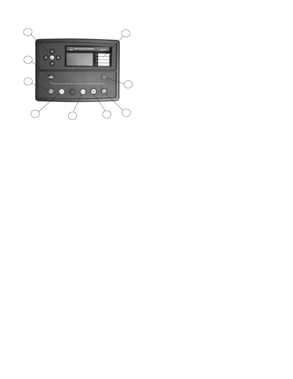
DSE 7310 CONTROLLER
A. MENU NAVIGATION BUTTONS – Left and Right buttons select
different grouping (i.e. Engine reading Generator readings, etc)
Up and down buttons scroll through the different reading for each
group.
B. STOP/RESET – This button places the module into its STOP/
RESET mode. This will clear an alarm conditions for which the
triggering criteria have been removed. If the engine is running
and this button is pushed the module will shut off the fuel solenoid
and the engine will come to a stop. If a remote start signal is
received while this switch is activated, the unit will not start.
C. MANUAL - This mode allows manual control of the generator
functions. Once in the MANUAL mode the module will allow you
to start the unit using the START button. The unit will continue
to run until either the STOP/RESET or AUTO button is pressed.
If the unit receives a remote start signal during manual opera-
tion, the generator will remain running even after the remote start
signal has been lost. You must use the STOP/RESET or AUTO
button to stop the unit once you have started it in manual mode.
**** CAUTION ****
IF THE POWER FAILS WHILE RUNNING IN THE MANUAL
MODE THE TRANSFER SWITCH WILL TRANSFER THE LOAD
TO THE GENERATOR. TO PREVENT THIS THE MAINLINE CIR-
CUIT BREAKER ON THE GENERATOR MUST BE OPENED.
D. AUTO – This button places the module into its AUTOMATIC
mode. This module will monitor the remote start input for a relay
closure. When the remote start signal is received it will time out
the start delay (5 Seconds) and then start the engine generator
set. When the remote start signal is lost (relay opened up) the
module will shut the engine generator set down after the cool
down timer has timed out. The module will return to the auto start
mode and await the next start signal.
E. LAMP TEST/HORN RESET - This button silences the audible
alarm if it is sounding and illuminates all of the LEDs as a lamp
test feature. When configured and fitted to a compatible engine
ECU, pressing this button in STOP/RESET mode after pressing
the START button (to power the ECU) will cancel any “passive)
alarms on the engine ECU.
F. START – This button is active only in the MANUAL or STOP/
RESET mode. Pressing this button in the MANUAL mode will
start the engine locally for testing. The engine will continue to
run until either the STOP/RESET or the AUTO button is pressed.
Pressing this button with the control in the STOP/RESET mode
will turn on the CAN engine ECU (when correctly configured and
fitted to a compatible engine ECU)
G. CLOSE GEN-SET – NOT USED IN THIS APPLICATION
H. OPEN GEN-SET – NOT USED IN THIS APPLICATION
J. USER CONFIGURABLE INDICATORS –
1. Remote Start
2. Fuel Selection on for LP - off for NG.
3. Generator Available
4. Emergency Stop.
NOTE: STOP/RESET, MANUAL mode and AUTO mode buttons
all have indicator lamps next to them to tell you what mode you
are in. Pressing buttons out of sequence will cause the engine
not to do what you may think it should be doing. See button op-
eration sequencing above.
INITIAL START UP
****************
***** WARNING *****
****************
EQUIPMENT DAMAGE - DO NOT jump start these engine gen-
erator sets. Starting these units on a low battery or jump starting
them will cause damage to the engine control module.
Use the following check list to verify correct installation before
starting the engine:
Note: A roof access panel has been provided to check/fill
the engine coolant. Side panels may be removed by opening
the latches on the top of the side panels.
1. Engine oil. Fill as required with proper grade/qty.
2. Engine coolant. Fill as required with proper
mixture.
3. Unit mounting base properly bolted down.
4. Clearance for service and maintenance on all
sides.
5. Proper fuel line material and size.
6. All fuel line connections tight.
7. Fuel line protected and a moisture trap installed
(may be required for N.G.).
8. Correct LP/NG pressure 4-6 Oz. (7-11" Wc).
9. Battery connections clean and tight.
10. Battery fully charged.
11. All AC and DC wiring installed and properly
protected.
After completing the above checklist, the engine-generator set is
ready for the initial start-up test.
Page 10
2090-00
60706-227
DSE 7310 CONTROLLER
A. MENU NAVIGATION BUTTONS – Left and Right buttons select
different grouping (i.e. Engine reading Generator reading, etc) Up
and down buttons scroll through the different reading for each
group.
B. STOP/RESET – This button places the module into its STOP/
RESET mode. This will clear an alarm conditions for which the
triggering criteria have been removed. If the engine is running
and this button is pushed the module will shut off the fuel sole-
noid and the engine will come to a stop. If a remote start signal is
received while this switch is activated, the unit will not start.
C. MANUAL - This mode allows manual control of the generator
functions. Once in the MANUAL mode the module will allow you
to start the unit using the START button. The unit will continue to
run until either the STOP/RESET or AUTO button is pressed. If
the unit receives a remote start signal during manual operation,
the generator will remain running even after the remote start
signal has been lost. You must use the STOP/RESET or AUTO
button to stop the unit once you have started it in manual mode.
**** CAUTION ****
IF THE POWER FAILS WHILE RUNNING IN THE MANUAL
MODE THE TRANSFER SWITCH WILL TRANSFER THE LOAD
TO THE GENERATOR. TO PREVENT THIS THE MAINLINE
CIRCUIT BREAKER ON THE GENERATOR MUST BE OPENED.
D. AUTO – This button places the module into its AUTOMATIC
mode. This module will monitor the remote start input for a relay
closure. When the remote start signal is received it will time out
the start delay (5 Seconds) and then start the engine generator
set. When the remote start signal is lost (relay opened up) the
module will shut the engine generator set down after the cool
down timeR has time out. The module will return to the auto start
mode and await the next start signal.
E. LAMP TEST/HORN RESET - This button silences the audible
alarm if it is sounding and illuminates all of the LEDs as a lamp
test feature. When configured and fitted to a compatible engine
ECU, pressing this button in STOP/RESET mode after pressing
the START button (to power the ECU) will cancel any “passive)
alarms on the engine ECU.
F. START – This button is active only in the MANUAL or STOP/
RESET mode. Pressing this button in the MANUAL mode will
start the engine locally for testing. The engine will continue to run
until either the STOP/RESET or the AUTO button is pressed.
Pressing this button with the control in the STOP/RESET mode
will turn on the CAN engine ECU (when correctly configured and
fitted to a compatible engine ECU)
G. CLOSE GEN-SET – NOT USED IN THIS APPLICATION
H. OPEN GEN-SET – NOT USED IN THIS APPLICATION
J. USER CONFIGURABLE INDICATORS –
1. Remote Start
2. Fuel Selection on for LP - off for NG.
3. Generator Available
4. Emergency Stop.
NOTE: STOP/RESET, MANUAL mode and AUTO mode buttons
all have indicator lamps next to them to tell you what mode you
are in. Pressing buttons out of sequence will cause the engine
not to do what you may think it should be doing. See button
operation sequencing above.
INITIAL START UP
****************
***** WARNING *****
****************
EQUIPMENT DAMAGE - DO NOT jump start these engine
generator sets. Starting these units on a low battery or jump
starting them will cause damage to the engine control module.
Use the following check list to verify correct installation before
starting the engine:
Note: Roof access panels have been provided to check/fill
the engine oil and the coolant. Side panels may be removed
by removing the thumb screws on the bottom under side of
each panel.
1.
Engine oil. Fill as required with proper grade/qty.
2.
Engine coolant. Fill as required with proper
mixture.
3.
Unit mounting base properly bolted down.
4.
Clearance for service and maintenance on all
sides.
5.
Proper fuel line material and size.
6.
All fuel line connections tight.
7.
Fuel line protected and a moisture trap installed
(may be required for N.G.).
8.
Correct LP/NG pressure 4-6 Oz. (7-11" Wc).
9.
Battery connections clean and tight.
10.
Battery fully charged.
11.
All AC and DC wiring installed and properly
protected.
After completing the above checklist, the engine-generator set is
ready for the initial start-up test.
A
B
C
D
F
E
G
H
J
1
2
3
4