Serial communication, 5 serial communication – Casio IT-2000W User Manual
Page 42
42
2.3.5 Serial Communication
Available Interfaces
Port
I/O Address
Name
Uses
Remark
COM1
3F8h-3FFh
8-pin serial I/F
Connection with a barcode
reader or PC
14-pin serial I/F
Connection with an
expansion I/F device
COM2
2F8h-2FFh
IrDA 1.0
Communication with an I/O
Box or between two IT2000s
Can be switched
via the system
library.
COM3
3E8h-3EFh
(Modem card)
Modem card
If a modem card is
used.
COM4
2E8h-2EFh
IrDA 1.1
Communication with an I/O
Box or between two IT2000s
Direct control not
possible
COM1
This is a COM port for RS-232C communication. This port can be used after turning on the power to
the 8-pin serial I/F via the system library. The 8-pin serial I/F is located on the side panel of the main
unit.
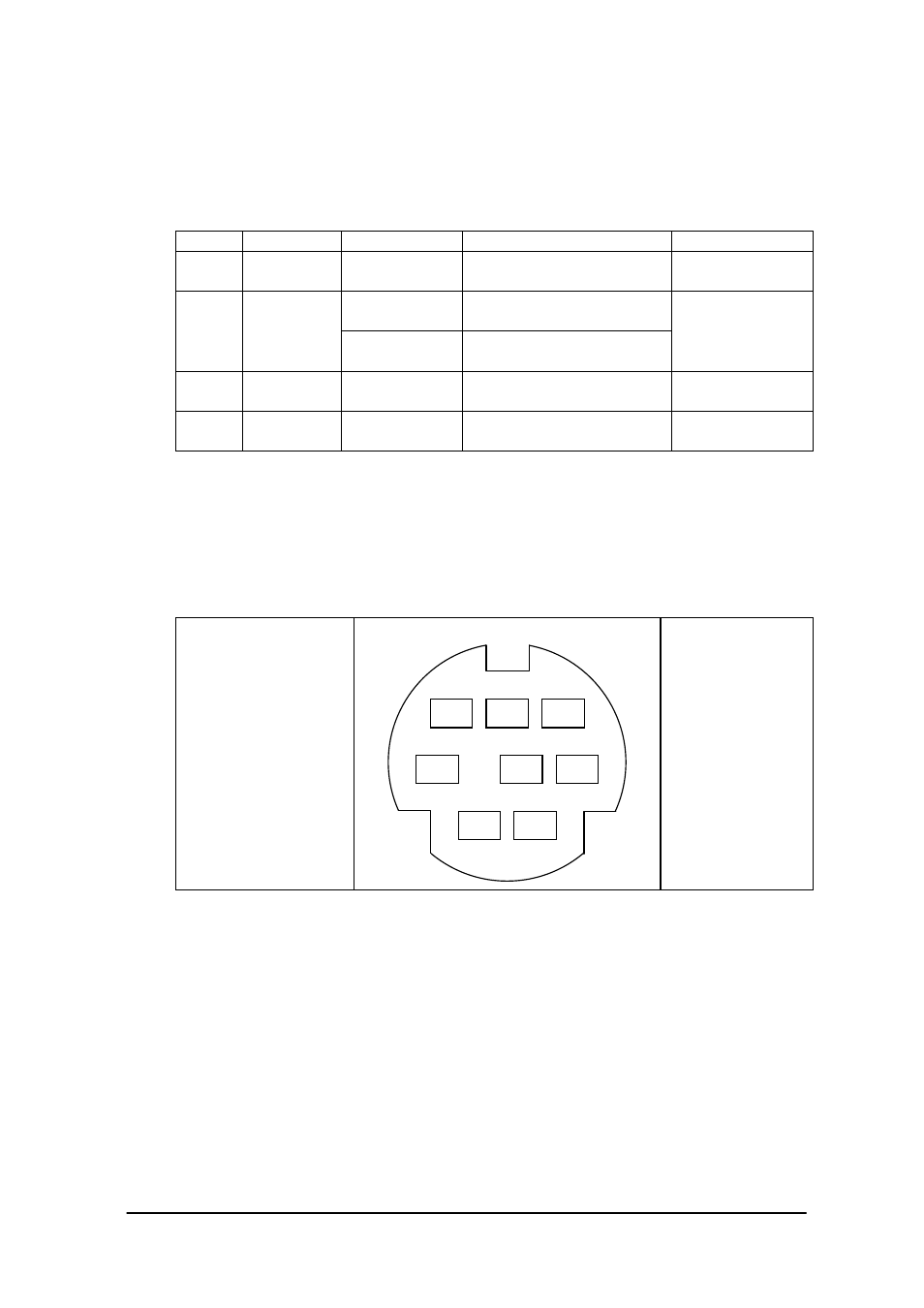
Pin assignment
Pin 1. SD
Pin 2. RD
Pin 3. RS
Pin 4. CS
Pin 5. Vcc
Pin 6. GND
Pin 7. ER
Pin 8. DR
Fig. 2.10