Ab b c c, Vtr8300 fan coil controller application guide – Viconics VTR8300 Line Voltage Application Guide User Manual
Page 20
VTR8300 Fan Coil Controller
Application Guide
20
Viconics Technologies Inc.
|
9245 Langelier Blvd.
|
St.-Leonard
|
Quebec
|
Canada
|
H1P 3K9
|
Tel: (514) 321-5660
|
Fax: (514) 321-4150
028-6047-03
www.viconics.com
|
February 2015
©
2
01
5 V
ic
onic
s T
ec
hno
lo
gi
es
Inc
. A
ll r
ig
ht
s r
ese
rv
ed
.
The PIR can maximize
your energy saving from
10-30% by relaxing
temperature set points in
unoccupied zones during
scheduled periods.
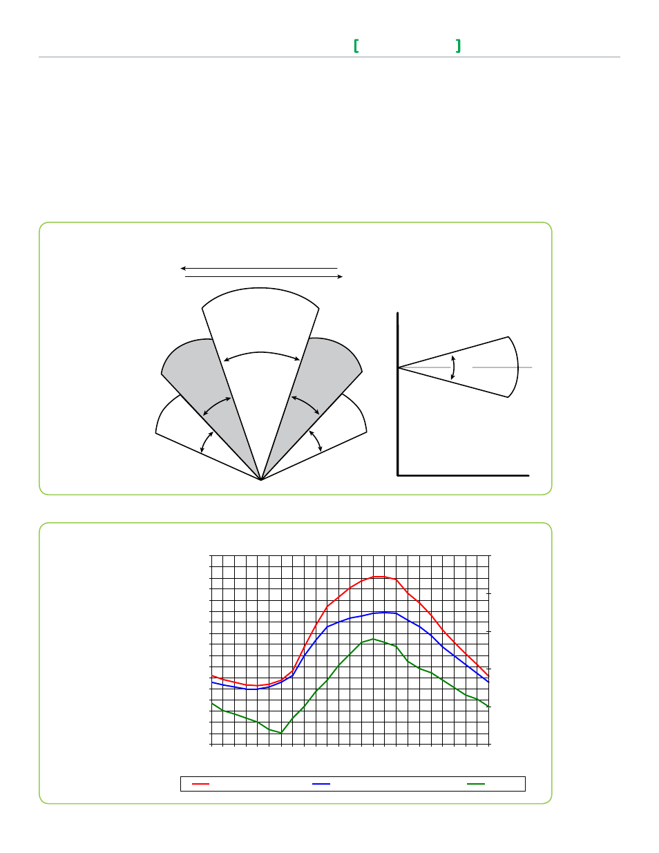
Typical Savings of 10-30%
0
5
10
15
20
25
30
35
40
45
50
55
60
65
70
75
80
85
0
2
4
6
8
10
12
14
16
18
20
22
24
Time of Day (EST)
En
er
gy
U
sa
ge
(K
Wh
)
0%
10%
20%
30%
40%
50%
Savi
ng
P
er
cen
tag
e
Typical Consumption
PIR Thermostat Consumption
Savings
AppendiX A - pAssive inFrA-red (pir) moTion deTeCTor Cover speCiFiCATions
Initially, the controller is in Stand-by mode. Stand-by setpoints are used at the controller. As soon as the
PIR detects motion, the Occupancy status switches to Occupied and the Stand-By Time timer is reset. The
Occupied setpoints are used. If no motion is detected in the room for the entire Stand-By Time duration
(adjustable parameter), the room then switches to Stand-by mode and stand-by setpoints are used. While in
Stand-by mode, if no motion is detected for the entire Unoccupied Time period (adjustable parameter), the
room switches to Unoccupied mode and uses its Unoccupied setpoints. While in Stand-By or Unoccupied
mode, any motion will switch the room back to Occupied mode.
PIR cover sequence of operation
Typical Detection Pattern for PIR Lens
Energy savings
20
O
20
O
20
O
20
O
40
O
A
B
B
C
C
Horizontal Angles (Typical)
Transverse motion: 4-5 ft/s
/
1.5 m/s
Recommended installation
height for PIR sensor:
4 - 5 ft. / 1.2-1.5 m
Sensor Ranges
A = 20 ft. / 6.1 m
B = 14 ft. / 4.3 m
C = 11 ft. / 3.4 m
Center
30
O
Vertical Angle (Typical)
Center