USL ECI-60 User Manual
Page 4
- 6 -
- 7 -
ECI Background:
The Electronic Cinema Interface (ECI) is designed to select a single input from a
variety of sources and then feed the selected source into a cinema processor. The
ECI provides inputs from 6 Channel Analog, 2 Channel Analog, 8 Channel Digital,
Toslink, and two SPDIF sources. The output is fed into the host cinema proces-
sor’s External Analog Input (6 Channels). A balanced 2 channel analog output of
AES channels 7 and 8 is provided.
Additionally, to synchronize the audio to the video source, each channel is capable
of up to 300ms delay. Input Delays – Each stage channel L, C, R, SW) is capable
of up to 200ms delay allowing for projector delay . Surround Delays - For the sur-
round channels (LS, RS), an additional delay of up to 100ms may be added to the
Input Delay. Delays can be confi gured for each type of input.
When a digital format is not selected an additional input allows a 6 channel analog
signal to bypass the ECI and be fed directly into the cinema processor’s External
Analog Input.
Input trim gains of up to 18dB may be added to the 2 and 6 Channel Analog Inputs.
There are no input trims on the digital inputs.
Output Trim attenuation of up to 20dB may be applied to each of the Digital
Modes.
Environmental Conditions:
Operating: 0 decrees C to 40 degrees C (32F to 104F)
Storage: 0 degrees C to 85 degreesC (32F to 185F)
Humidity: 20% to 80% relative, noncondensing.
Power Requirements:
100-240 VAC, 50-60 Hz, 300mA
Specifi cations:
One rack unit chassis.
Front Panel: 19 X 1.72 (431.8 X 43.688 mm)
Chassis: 17 X 1.67 X 7.5 (431.8 X 42.418 X 190.5 mm)
Weight: 6.35 lbs. (2.880 kg)
Shipping weight: 10 lbs. (4.536 kg)
Shipping Size: 24” x 17” x 6” (609.6 x 431.8 x 152.4 mm)
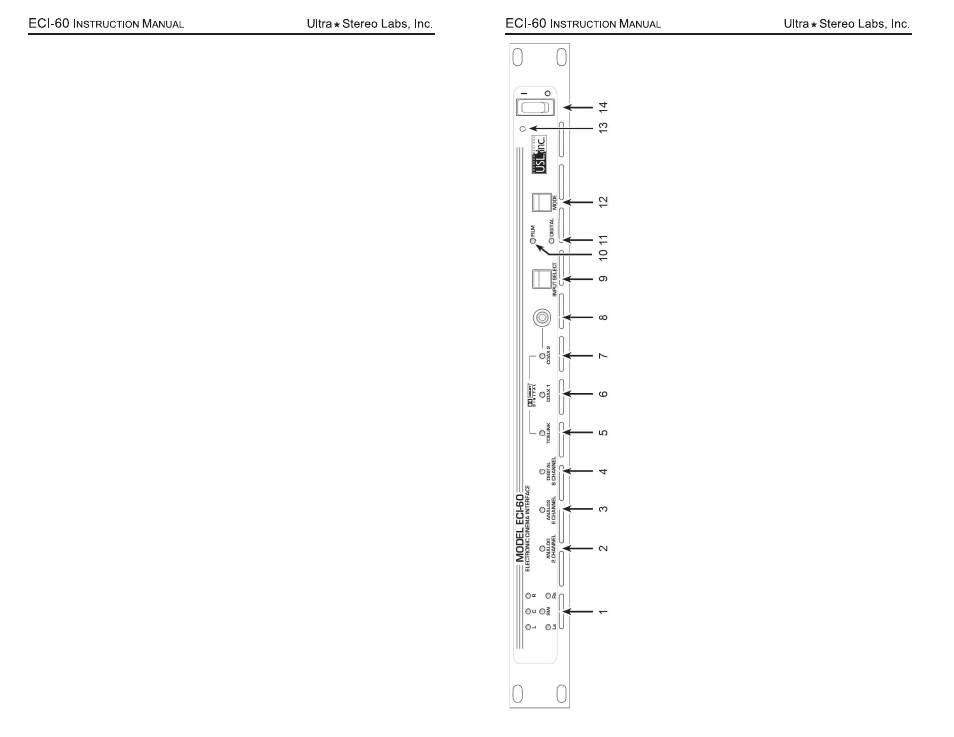
Signal presence indicators – Indicates when signals are greater than -30dB.
2 Channel
Analog Indicator – Balanced line input.
The 2 inputs are fed to a Pro Logic II decoder which produces a
6 channel output.
6 Channel
Analog Indicator – Balanced line input.
All channels (L, C, R, SW
, Ls, Rs) are processed through the
unit.
8 Channel Digital Indicator –
AES Balanced line input.
The standard 6 channels are processed through the unit.
T
wo spare channels have independent balanced line outputs for use as needed.
T
oslink Indicator –
An optical
fi
ber connection for SPDIF (PCM) or
AC3 signals.
T
w
o channel PCM is decoded by
the Pro Logic II into 6 channels.
COAX 1 Indicator – Rear Panel RCA
type connector for SPDIF (PCM) or
AC3 signals.
T
wo channel PCM is decoded
by the Pro Logic II into 6 channels.
COAX 2 Indicator – Front Panel RCA
type connector for SPDIF (PCM) or
AC3 signals.
T
wo channel PCM is de-
coded by the Pro Logic II into 6 channels.
COAX 2 Input – RCA
type connector for SPDIF (PCM) or
AC3 signals.
Input Select switch (Front Panel) – Steps through the Input choices.
Film Mode Indicator – Lights when the unit is in Film (Bypass) Mode. Signals from
Analog Bypass Input pass directly
through the unit.
Digital Mode Indicator – Lights when the unit is in the Digital Mode. Signals from the selected digital input (item #9)
are processed through the unit.
Mode switch – Selects between Film or Digital Modes.
Power Indicator – Lights when unit is powered on.
Power Switch –
Applies power to the unit.
1.
2.
3.
4.
5.
6.
7.
8.
9.
10.
11.
12.
13.
14.