General, Installation – Twin City Gravity Relief / Intake Ventilators - IM-4700 User Manual
Page 2
2
Twin City Fan IM 4700
Receiving, Inspection & Unpacking
General Installation
Service Clearance
Unit Installation
When the equipment is received all items should be
carefully checked against the bill of lading to be sure all
crates and cartons have been received. Before accept-
ing delivery, carefully inspect each carton or crate for
visible shipping damage. If any damage is noticed, the
carrier should make the proper notation on the delivery
receipt acknowledging the damage. Make notations of all
damage on all copies of the bill of lading and have all
copies countersigned by the delivering carrier. The car-
rier should also fill out a Carrier Inspection Report. The
factory Traffic Department should then be contacted.
File claim for damage with the carrier. Physical damage
to the unit after acceptance is not the responsibility of
Twin City Fan Companies, Ltd.
Unpack each carton or crate and verify that all required
parts and proper quantities of each item have been
received. Refer to drawings for part descriptions. Report
shortages or missing items to your local representative
to arrange for replacement parts
Due to availability of carriers and truck space, it is not
possible to guarantee that all items will be shipped
together. Verification of shipments must be limited to
only those items on the bill of lading.
CAUTION: Sheet metal parts, screws, clips and similar
items inherently have sharp edges, and it is necessary
that the installer and service personnel exercise caution.
The installation of this equipment shall be in accordance
with the regulations of authorities having jurisdiction and
all applicable codes.
Adequate clearance around the unit should be kept for
safety, maintenance, and proper unit operation.
A minimum clearance of 36" to 48" is recommended
to insure proper ventilation. Unit should be installed
remote from building air exhausters to inhibit ingestion
of exhaust air into building.
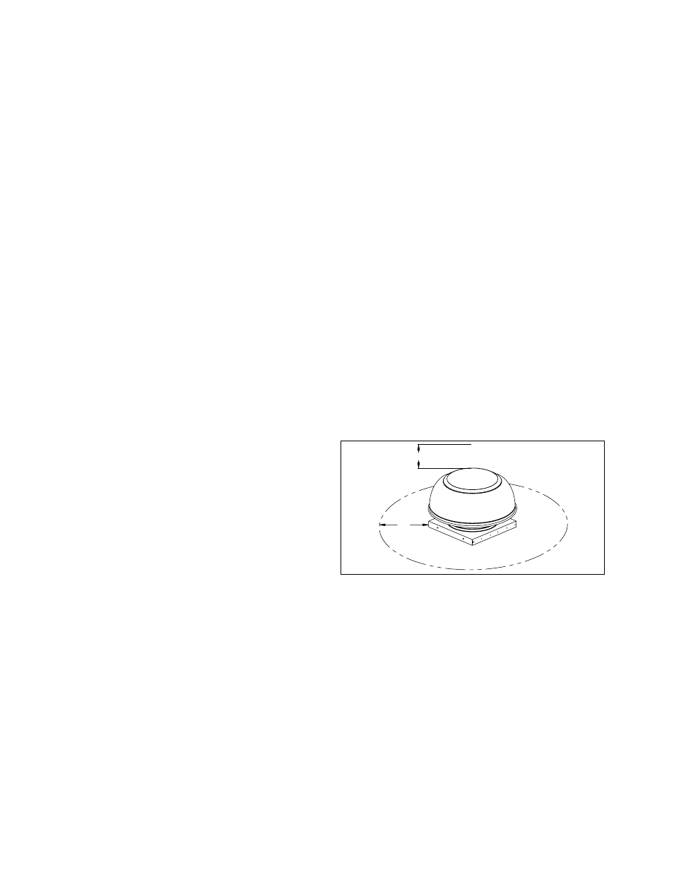
Allow a minimum of 24" clearance above the unit for
removal of unit top cover. Note: Clearance may have to
be increased if using the hinged curb option.
The unit must not be installed under any obstructions.
This equipment is to be installed by an experienced
installation company and fully trained personnel.
The mechanical installation of the exhaust ventilator
consists of making final connections between the unit,
building services, and duct connections.
24"
36"
Figure 1. Service Clearances
General
1. The unit should be roof mounted only to an appro-
priately sized roof curb or duct. See "Roof Curb
Installation" on page 3.
2. The base of the curb cap should be horizontal.
Installation
1. Drill 8 holes (2 per side) into the roof curb through
the holes provided in the unit curb cap.
2. Bolt the unit to the roof curb through these holes
using
1
⁄
4
-20 self-tapping screws.
Model GRV shown