General installation, Check, test & start procedure, Electrical connection – Twin City DBS / DBT Forward Curved Inline Duct Blowers - IM-4220 User Manual
Page 2: Warning
2
Twin City IM-4220
General Installation
CAUTION: Sheet metal parts, screws, clips and similar
items inherently have sharp edges, and it is necessary
that the installer and service personnel exercise cau-
tion.
The installation of this equipment shall be in accordance
with the regulations of authorities having jurisdiction and
with all applicable codes.
This equipment is to be installed by an experienced
installation company and fully trained personnel.
The mechanical installation of the inline centrifugal fan
consists of making final connections between the unit,
building services, and duct connections.
Check, Test & Start Procedure
WARNING
Electric shock hazard. Could cause severe injury or
death. Failure to bond the frame of this equipment
to the building electrical ground by use of the
grounding terminal provided or other acceptable
means may result in electrical shock. Disconnect
electric power before servicing equipment. Service
to be performed only by qualified personnel.
BEFORE START-UP: Disconnect power to this unit
before servicing the unit.
1. Check to verify that the wheel is free to rotate.
2. Verify that supply voltage on the line side of discon-
nect agrees with voltage on fan data plate and is
within the 10% utilization voltage.
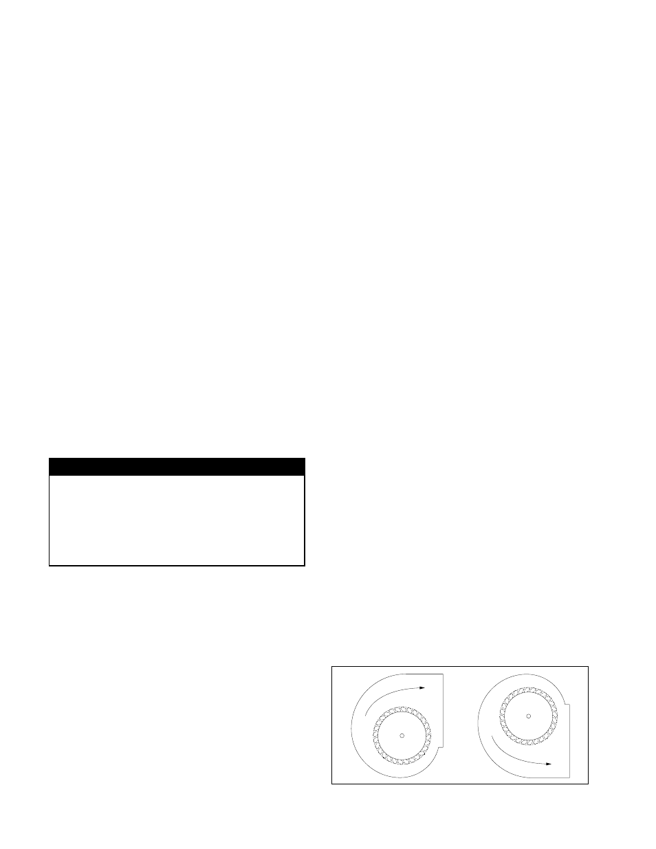
3. Apply power to unit and check rotation of wheel with
the directional arrow on the unit. See Figure 1.
WARNING: Rotation is critical. If allowed to operate
in the wrong direction, the motor will overload and
burn out.
WARNING: Check units for rotation. For three-phase,
rotation can be changed by interchanging any two of
the three line leads. If unit is checked on temporary
Figure 1. Fan Wheel Rotation
Electrical Connection
1. Connect supply wiring to the disconnect switch
(non-fused standard). Check the wiring diagrams on
the motor for connections.
2. The motor is factory set at the voltage marked on
the fan nameplate. Check the line voltage with the
nameplate voltage and wiring diagrams.
3. The main power wiring should be sized for the
ampacity shown on the dataplate. Size wires in
accordance with the ampacity tables in Article 310
of the National Electrical Code. If long wires are
required, it may be necessary to increase wire size
to prevent excessive voltage drop. Wires should be
sized for a maximum of 3% voltage drop.
CAUTION: Use copper conductors only.
CAUTION: Protect wiring from sharp edges. Leave
some slack in the line to prevent damage.
4. Disconnect switches are not fused. The power leads
must be protected at the point of distribution in
accordance with the fan dataplate.
5. On fans without a thermal protector integral to the
motor (refer to unit or motor dataplate to determine
if protector is present) a separate overload device
is required. Refer to Sections 430-32 of the N.E.C.
for sizing.
6. All units must be electrically grounded in accordance
with local codes or, in the absence of local codes,
with the latest edition of the National Electrical
Code (ANSI/NFPA 70). A ground lug is provided as
standard in the unit terminal box. Size grounding
conductor in accordance with Table 250-95 of the
National Electrical Code.
DO NOT use the ground
lug for connecting a neutral conductor.
7. Supply voltage to the inline fan should not vary by
more than 10% of the value indicated on the unit
dataplate. Phase unbalance must not exceed 2%.
WARNING: Failure of motor due to operation on
improper line voltage or with excessive phase unbal-
ance constitutes product abuse and may cause
severe damage to the unit’s electrical components.
wiring, it should be rechecked when permanently
installed. Motor burn-out or tripped overload protec-
tion devices are usually the result of wrong rotation.
4.
Electrical Input Check: Perform check of fan ampere
draw and verify that motor nameplate amps are not
exceeded. Take into account the service factor range
if motor is nameplated above a 1.0 service factor.
5. Fan RPM should be checked and verified with a
tachometer.
NOTE: The fan was balanced at the factory to be
within stringent vibration levels before shipment.
However, there are several things that may cause
vibration, such as rough handling in shipment and
installation, weak foundations and alignments.
Rotation
Rotation