Fan installation – factory assembled units, Assembly of fans and sealing/isolation strips, Fan operation - safety – Twin City MPQN/MPQS Modular Plenum Fans - ES-110 User Manual
Page 3
3
Twin City Engineering Supplement ES-110
Fan Installation – Factory Assembled Units
Follow.proper.handling.instructions.given.earlier.
1..Move.the.fan.to.the.final.mounting.position.
2..Remove.skid,.crates,.and.packing.materials.carefully.
3..If.supplied,.place.vibration.pads.or.isolation.base.on.
mounting.bolts..Line.up.holes.in.fan.base.with.bolts.
4..Place.fan.on.mounting.structure..Carefully.level.unit.
using. shims. as. required. at. all. mounting. hole. loca-
tions..Bolt.down.the.unit.
Assembly of Fans and Sealing/Isolation
Strips
1..Fans.must.be.securely.bolted.to.a.base.either.directly.
through.the.factory.mounting.holes.or.with.a.properly.
designed. clip.. Final. bolting. of. layer. of. fans. to. the.
support. structure. or. base. should. be. done. after. the.
individual.fans.are.bolted.together.as.a.row.
2..During. installation. rubber. strips. need. to. be. installed.
between. each. fan.. Use. double-sided. foam. tape. to.
hold. strips. in. place. during. installation.. Two. (2). to.
three.(3).pieces.of.tape.can.be.used.as.needed.for.
this. purpose. (each. end. and. middle. of. rubber. strip)..
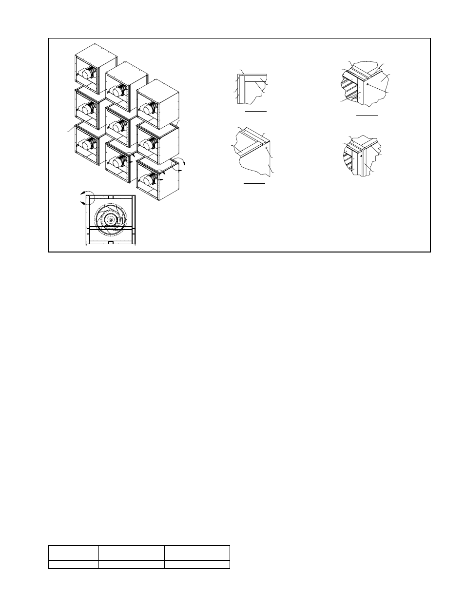
Location.of.these.strips.is.documented.in.Figure.2.
3..The.first.fan.on.the.bottom.row.will.have.the.2.verti-
cal. strips. placed. next. to. the. mounting. holes.. Note:.
Strips.should.be.cut.to.ensure.an.airtight.seal.between.
fans.
4..The.bolts.to.be.snugged.up.on.vertical.sections.for.the.
first.row..Once.all.strips.are.in.place,.the.bolts.shall.
be.tightened.to.torque.values.in.table..See.Table.1.
5..The.bolts.holding.the.fan.to.the.supporting.structure.
can.now.be.torqued.
6..Rubber.strips.are.then.placed.on.the.top.of.the.fan.
to.support.the.fan.above.it.according.to.the.pattern.
shown.. Note:. On. larger. fan. assemblies. 2. strips. are.
used.in.the.back.to.support.the.weight.of.the.motor.
7..The.second.row.and.succeeding.rows.can.be.installed.
using.the.same.assembly.steps.as.the.first.row.
8..Rubber.strips.are.not.normally.needed.on.the.outside.
or.top.of.the.parralel.fan.system.
9..Sealing.around.the.perimeter.should.be.accomplished.
using.a.flexible.material.
Fan Operation - Safety
For. general. safety. practices. for. air. moving. equipment,.
see.AMCA.Bulletin.410.
. Twin. City. Fan. &. Blower. has. many. safety. accesso-
ries.available..These.safety.devices.include.(but.are.not.
limited.to).inlet.and.discharge.screens..The.use,.abuse,.
or.non-use.of.safety.devices.is.the.responsibility.of.the.
purchaser.
. Facility-related. safety. conditions. include. fan. acces-
sibility.and.location..How.easily.can.non-service.person-
nel. access. the. unit?. Is. the. fan. in. a. hazardous. duty.
environment?.Was.the.unit.ordered.for.this.duty?.Other.
concerns. must. also. be. addressed.. All. fans. should. be.
powered.through.switches.which.are.easily.accessible.to.
service.personnel.from.the.fan..Every.switch.should.have.
the.ability.to.be.“locked-off”.by.the.service.person.and.
the.key.to.be.retained.by.this.person.to.prevent.acci-
dental.power.of.the.fan.while.service.is.in.process.
Figure 2.
MOUNTING HOLE
OUTER SHELL
RUBBER GASKET
RUBBER GASKET
OUTLET ONLY
222 & ABOVE
FRAME
FRAME
PERF. PLATE
RUBBER GASKET
RUBBER GASKET
RUBBER GASKET
RUBBER GASKET
RUBBER GASKET
RUBBER GASKET
NOTE 5
OUTER SHELL
RUBBER GASKET
RUBBER GASKET
OUTER SHELL
OUTER SHELL
MOUNTING HOLE
DETAIL C
DETAIL A
DETAIL D
DETAIL B
A
NOTES
RUBBER GASKET
D
B
C
NOTES:
1. On the horizontal between fans, one strip of gasket material is needed on inlet side & two
on drive end on 222 & above, 200 and below get one strip on each end.
2. Gaskets need to connect in all corners to ensure proper sealing.
3. Rubber gasket is to be placed directly next to the mounting holes on the inlet and drive side.
4. Rubber gasket is 1/2 in. x 2 in. x cut-to-fit.
5. Rubber gasket is to be held in place be double-stick foam tape during assembly.
RUBBER GASKET
Table 1. Torque Values MPQN/MPQS Fasteners
Size
Net Type
Torque Values
(ft lbs)
3/8.–.16.UNC
Nylock
16.–.17