Fan operation - safety, 4twin city engineering supplement es-52, Figure 7. wheel-funnel overlap – Twin City Centrifugal Fans - ES-52 User Manual
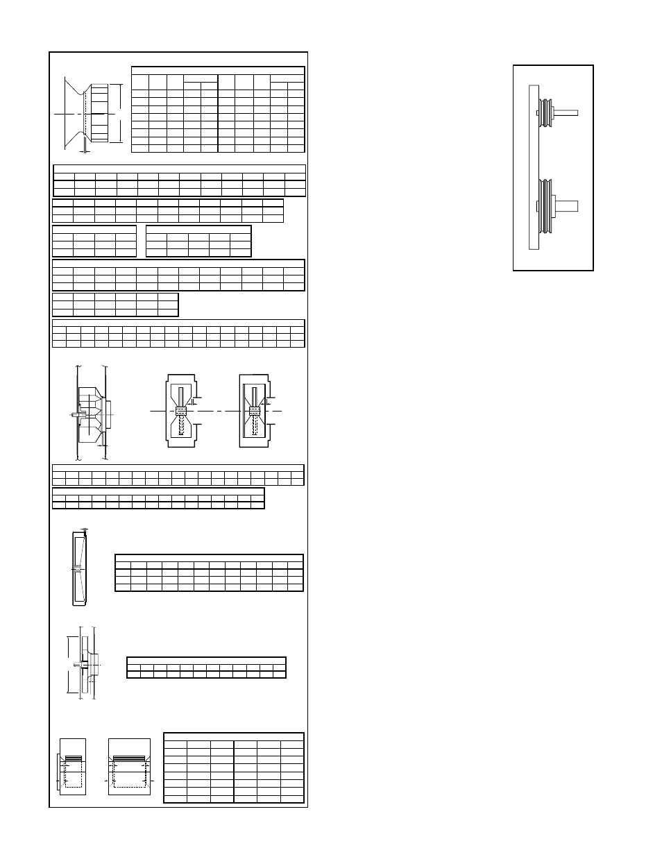
Page 4: Figure 6. sheave alignment
4
Twin City Engineering Supplement ES-52
.
RBO, RBR Wheel Placement
Size 913 915 917 919 921 923 926 929 933 937 941 945 949 954 960
B
0.53 0.53 0.59 0.69 0.78 0.88 0.97 1.03 1.22 1.38 1.56 1.69 1.81 1.88 2.16
the. key. should. be. placed. in.
the.keyway.pushed.toward.the.
bearing. as. far. as. the. runout.
will. allow. without. rubbing.. The.
back. of. the. sheave. should. be.
lined. up. with. the. end. of. the.
key. (see. Figure. 5. on. page. 3)..
For.sheaves.without.a.key,.the.
sheave. should. be. placed. as.
close. to. motor. and/or. bearing.
as. possible. without. rubbing..
Typically. the. sheave. should.
be. at. least. ¼". away. from. the.
motor,. bearing,. guard,. struc-
tures,.etc.
c..Align. sheaves. with. a. straight-
edge.extended.along.the.perim-
eters. of. both. sheaves,. just.
making. contact. in. two. places.
on. outside. perimeters. of. both.
sheaves.(see.Figure.6).
d..Tighten.down.sheave.bolts.
e..Install.a.matched.set.of.belts..Slide.the.motor.to.
obtain. slack. and. tighten. belts.. Using. a. pry. will.
damage.belts.
f... Tighten.belts.to.proper.belt.tension..Ideal.tension.
is. just. enough. tension. so. that. belts. do. not. slip.
under.peak.load..Recheck.sheave.alignment.
g..After.initial.installation.of.belts,.recheck.belt.tension.
again.after.a.few.days.to.adjust.belt.tension..(New.
belts.require.a.break-in.period.of.operation.)
10..Install. any. safety. devices. or. accessories. supplied..
(Accessories. commonly. used. are. inlet. vanes,. shaft.
seals.and.shaft.coolers,.plugs,.dampers,.and.inlet.or.
discharge.screens..Refer.to.appropriate.documents.
in.appendix.)
11..Grout. may. now. be. applied.. Grout. is. used. to. dis-
tribute.loads.and.should..not.be.used.as.the.sole.
support.of.any.rotating.equipment.
12..When.connecting.the.fan.to.the.system,.it.is.recom-
mended.that.the.inlet.and.discharge.be.isolated.from.
the.system.with.flex.connections.(where.practical).to.
block. transmitted. vibration.. All. duct. connections. to.
the.fan.should.be.independently.supported..Do.not.
use.fan.to.support.duct.
Fan Operation - Safety
For. general. safety. practices. for. air. moving. equipment,.
see.AMCA.Bulletin.410.
. Twin. City. Fan. &. Blower. has. many. safety. accesso-
ries.available..These.safety.devices.include.(but.are.not.
limited.to).belt.guards,.shaft.guards,.inlet.and.discharge.
screens..The.use,.abuse,.or.non-use.of.safety.devices.
is.the.responsibility.of.the.purchaser.
. Facility-related. safety. conditions. include. fan. acces-
sibility.and.location..How.easily.can.non-service.person-
nel. access. the. unit?. Is. the. fan. in. a. hazardous. duty.
environment?.Was.the.unit.ordered.for.this.duty?.Other.
concerns. must. also. be. addressed.. All. fans. should. be.
powered. through. switches. which. are. easily. accessible.
to.service.personnel.from.the.fan..Every.switch.should.
have.the.ability.to.be.“locked-off”.by.the.service.person.
and. the. key. to. be. retained. by. this. person. to. prevent.
accidental.power.of.the.fan.while.service.is.in.process.
A
DIA
B
RBO
RBR
B
B
B
A
B
A
B
A
SWSI
DWDI
Figure 7. Wheel-Funnel Overlap
HIB, RTF, HRT* Wheel Placement
Size
A
B
B*
Size
A
B
B*
19
23
19
23
180 20.50 0.31
—
.—
400 45.25 0.69 1.03 0.97
200 22.50 0.34
—
—
450 50.00 0.75 1.13 1.06
220 25.00 0.38
—
—
490 55.13 0.81 1.25 1.13
240 27.50 0.44
—
—
540 61.00 0.91 1.38 1.25
270 30.38 0.47 0.50 0.50 600 67.50 1.00 1.31 1.31
300 33.50 0.50 0.69 0.69 660 74.25 1.13 1.56 1.44
330 37.00 0.56 0.69 0.69 730 82.00 1.22 1.75 1.63
360 41.00 0.63 0.81 0.81 800 90.75 1.34 1.06 1.31
HIB, RTF, HRT, BC, BCS, TSL, BAF, BAE, EPF & EPQ
BC-SW, BC-DW, BCS, TSL, BAF SWSI & DWDI Wheel Placement
Size
122
135
150
165
182
200
222
245
270
300
330
A
12.25 13.50 15.00 16.50 18.25 20.00 22.25 24.50 27.00 30.00 33.00
B
0.32
0.34
0.38
0.44
0.56
0.63
0.69
0.75
0.88
0.97
1.06
RBA, RBO & RBR
FC
Size
365
402
445
490
542
600
660
730
807
890
A
36.50 40.25 44.50 49.00 54.25 60.00 66.00 73.00 80.75 89.00
B
0.94
1.03
1.13
1.25
1.38
1.56
1.69
1.88
2.09
2.28
EPF, EPQ, BAE SWSI & DWDI Wheel Placement
Size
182
200
222
245
270
300
330
365
402
445
490
A
19.00 20.82 23.16 25.51 28.11 31.23 34.36 38.00 41.90 46.33 51.01
B
0.38
0.41
0.46
0.50
0.55
0.62
0.68
0.75
0.83
0.91
1.01
Size
542
600
660
730
807
A
56.48 62.47 68.71 76.00 84.07
B
1.11
1.23
1.36
1.50
1.66
EPF, EPQ Wheel Placement
Size
122
150
165
A
13.00 14.13 16.16
B
0.25
0.25
0.25
BAE SWSI & DWDI Wheel Placement
Size
122
135
150
165
A
12.25 13.50 15.00 16.50
B
0.31
0.34
0.38
0.44
A
RBA
RBA Wheel Placement
Size 907 909 911 913 915 917 919 921 923 926 929 933 937 941 945 949 954 960
A
0.25 0.38 0.47 0.53 0.59 0.69 0.69 0.0
0.0
0.0
0.0
0.0
0.0
0.0
0.0
0.0
0.0
0.0
MBW, MBO & MBR
MBW, MBO, MBR Wheel Placement
Size 196
224
252
280
308
336
365
421
477
533
589
MBW 0.50 0.44 0.38 0.25 0.38 0.44 0.56 0.63 0.75 0.75 0.88
MBO 0.50 0.44 0.38 0.25 0.38 0.44 0.56 0.63 0.75 0.75 0.88
MBR 0.25 0.25 0.25 0.25 0.25 0.38 0.50 0.69 0.81 0.94 1.00
GAP
FC Wheel Placement
Size
A
B
Size
A
B
10.5
0.47
0.69
30
0.75
4.38
12
0.25
1.88
33
0.81
5.00
15
0.44
2.19
36
0.75
5.00
18
0.50
2.25
39
1.06
6.38
21
0.69
2.88
42
1.69
7.50
24
0.81
3.00
48
1.50
7.13
27
0.69
3.13
54
1.00
10.50
B
A
Dia.
BCN Wheel Placement
Size 270 300 330 365 402 445 490 542 600 660 730
B
0.09 0.09 0.13 0.13 0.13 0.16 0.16 0.19 0.22 0.22 0.25
BCN
APF & APQ Wheel Placement
Size 121
141
161
181
201
221
251
281
321
351
391
441
491
551
631
711
791
A
13.00 14.13 16.16 18.44 19.94 22.78 25.06 28.25 31.81 35.81 39.81 44.56 50.06 55.75 63.69 71.69 79.63
B
0.25 0.25 0.25 0.31 0.31 0.31 0.50 0.50 0.56 0.63 0.63 0.75 0.78 0.81 1.03 1.28 1.38
Note:.On.sizes.905-911.wheel.is.to.be.centered.in.housing.
*Use.second.'B'.columns.for.HRT-19.and.HRT-23.dimensions
Note:.On.sizes.421-589.wheel.is.to.be.centered.in.housing.
Figure 6.
Sheave Alignment