Maintenance, Troubleshooting, Motor – Twin City Electronically Commutated Motors - IM-4055 User Manual
Page 3
3
Twin City IM 4055
control range available for a given fan/motor combina-
tion, the motor mounted dial must be turned all the way
in the CW direction or to the maximum RPM available.
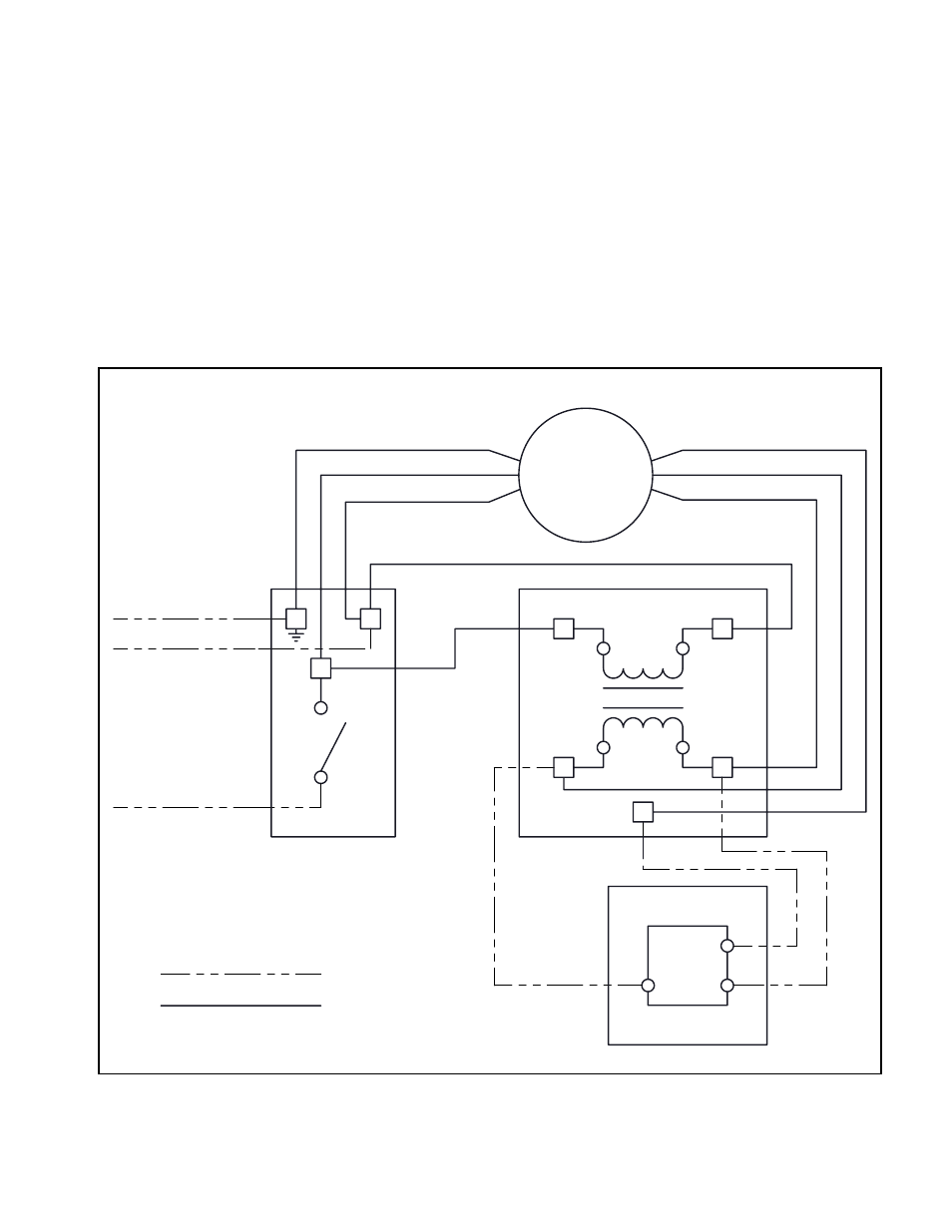
Figure 1 below is a detailed wiring diagram for the Re-
mote Mounted Dial option.
CAUTION: Always disconnect power before inspection or
maintenance. Although motor may be off and not running
when a 0-1.9V DC signal is present, high voltage will still
be present at the motor.
Figure 1. Remote Mounted Dial Wiring Diagram
24 VAC
REMOTE DIAL (TCF)
2
3
1
120 VAC
YELLOW
BLUE
COM
0 - 10 V
24 VAC
BLACK
WHITE
GROUND
SIGNAL
CONTROL
LEADS
POWER
LEADS
MOTOR
BLACK
WHITE
RED
DISCONNECT
BOX
GROUND
BLACK
WHITE
FACTORY PROVIDED
FIELD INSTALLED
Maintenance
Keep motor dry and free of dirt, dust and debris.
Troubleshooting
Remote Dial does not vary the motor speed
•
Verify that correct connections are made (refer to
page 2)
•
Make sure that the connections are solid
•
Check control input voltage at connection (inside
transformer box)
•
Make sure that the dial on the motor is opened CW
- Fans With CE Mark - ES-2-06 (16 pages)
- Protective Coatings Guide - ES-35 (4 pages)
- Bearing Problems - ES-53 (1 page)
- Airflow Measuring System Using Piezometer Ring - ES-105 (4 pages)
- Fans Using Taperlock Hub & Bushing - ES-106 (1 page)
- Troubleshooting Vibration Problems - ES-202 (1 page)
- ATEX Fans - ES-309 (2 pages)
- SWSI Nested Inlet Vanes - ES-394 (4 pages)
- Type ‘E’ Adjustable Pitch Propeller - ES-404 (2 pages)
- Aero Acoustic Diffuser - ES-409 (4 pages)
- DWDI Nested Inlet Vanes - ES-494 (4 pages)
- Torque Requirements - ES-495 (2 pages)
- External Inlet Vanes - ES-594 (2 pages)
- TSL; Nested Inlet Vanes - ES-694 (2 pages)
- Centrifugal Fans - ES-52 (8 pages)
- Air Kit Fans - ES-56 (2 pages)
- MPQN/MPQS Modular Plenum Fans - ES-110 (8 pages)
- Tubeaxial, Vaneaxial, & Duct Fans ES-191 (4 pages)
- Panel Fans & Power Roof Ventilators - ES-200 (2 pages)
- Heavy Duty Composite Fiber Fans - IM-410 (10 pages)
- Backward Inclined Hinged Restaurant Exhaust Fan - BHRE - IM-610 (12 pages)
- TSL & QSL; Inline Centrifugal and Mixed Flow Fans - ES-895 (8 pages)
- Heavy Duty Centrifugal Fans - ES-995 (8 pages)
- Centrifugal Fume Exhaust Fans - IM-390 (8 pages)
- Modular Plenum Fans - MPLFN / MPLFS / MPLQN / MPLQS - IM-495 (7 pages)
- Inline Fume Exhaust Fans - IM-1080 (8 pages)
- General Instructions (Fiberglass Ventilators) - IM-3000 (8 pages)
- HA / HAB Fiberglass Wall Mount Ventilators - IM-3100 (4 pages)
- Axial Roof Ventilators and Tubeaxial Fans - IM-4000 (8 pages)
- Centrifugal Roof & Wall Exhausters - IM-4050 (16 pages)
- BSI / DSI Square Inline Centrifugal Fans - IM-4205 (12 pages)
- DBS / DBT Forward Curved Inline Duct Blowers - IM-4220 (8 pages)
- BCFS Centrifugal Filtered Supply Fans - IM-4300 (4 pages)
- BCRFS Belt Driven Centrifugal Filtered Supply Fans - IM-4310 (8 pages)
- Gravity Relief / Intake Ventilators - IM-4700 (4 pages)
- Modular Gravity Hood - MGR, MGI - IM-4720NFL (4 pages)
- Modular Gravity Hood - MGR, MGI - IM-4720NFS (4 pages)
- Modular Gravity Hood - MGI with Filters - IM-4720FSL (4 pages)
- Modular Gravity Hood - MGI with Filters - IM-4720FSS (4 pages)
- TCPE, WPB, WPD Propeller Wall Fans - IM-4800 (16 pages)
- Hooded Tubeaxial Roof Fans (Non-Filtered) - IM-4850NF (4 pages)
- Hooded Tubeaxial Roof Fans (Filtered Supply) - IM-4850FS (4 pages)
- Hooded Propeller & Tubeaxial Roof Fans - IM-4860 (8 pages)
- Hooded Propeller Fans (Non-Filtered) - IM-4860NF (4 pages)