Speed control options – Twin City Electronically Commutated Motors - IM-4055 User Manual
Page 2
2
Twin City IM 4055
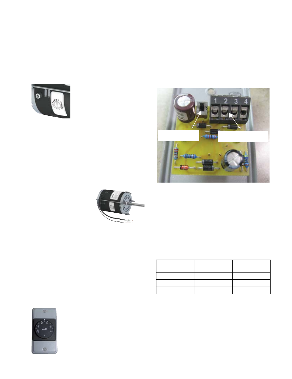
the remote mounted dial. The settings of the switch are
0-10V or 2-10V. A label on the rear of the controller’s
printed circuitboard describes the settings. The motor
will run regardless of which setting the dial is at, but
because the motor operates off of a 2-10V DC signal,
it will be off when a 0-1.9V DC signal is present. If the
user requires the remote mounted dial to turn off the
motor, the dial should be set at 0-10V DC.
With the field supplied 3 wire control cable connections
from the transformer box to the remote mounted dial
must be made as follows:
Connection in
Transformer Box
Description
Terminal on
Back of Dial
Yellow/White
Common
1
Blue/Black
24V AC
2
Red
0-10V DC
3
The user should verify that the dial is properly working
by adjusting the dial and checking that the motor speed
changes accordingly. The voltage at the dial should also
be verified. 24V AC should be present across terminal
1 and 2. Terminals 1 and 3 should have a DC voltage
in the range of 0-10V DC which should vary as the dial
is adjusted.
Note that the motor mounted dial acts as a speed ref-
erence for this option. In order to have the full speed
mote location of the controller. In addition, a standard
2x4 single gang electrical junction box (by others) is
required to mount the controller. The maximum distance
from the remote mounted controller to the motor is 100
feet. Distances greater than this could cause a loss of
the signal to the motor and result in unstable motor
performance.
On the back of the remote mounted dial there is a small
switch which will allow the user to change the output of
Three speed control options are available for the Twin
City Fan EC motor. Coming standard with the motor
is both a motor mounted dial, for speed adjustment at
the fan (first option), and a 0-10V DC control lead. The
0-10V DC control lead can be used with a remote speed
control, either field supplied (second option) or supplied
by TCF (third option).
1. Motor Mounted Dial – A potentiometer is mounted
to the motor housing offering full speed control range.
Speed adjustment is made with a
small flat head screwdriver. With
this option, the motor’s 0-10V DC
control leads are terminated in a
standard 2x4 junction box from the
factory and can remain there if not
required by the end user.
2. 0-10V DC Lead – A 36” long control lead is prewired
from the motor which accepts a 0-10V DC signal and
can be wired into building control systems or field sup-
plied controls. With this option, the control leads are ter-
minated in a standard 2x4 junction box from the factory.
Field supplied controllers should be provided and in-
stalled by others and send the motor a 0-10V DC signal.
A 24V AC source is also required to power the controls
in the motor. Note that the motor mounted dial acts as a
speed reference for this op-
tion. In order to have the full
speed control range available
for a given fan/motor com-
bination, the motor mounted
dial must be turned all the
way in the CW direction or to
the maximum RPM allowable
for the fan/motor combina-
tion (look for labels on fan). The motor operates off of
a 2-10V DC signal while the motor will be off when a
0-1.9V DC signal is present.
CAUTION: Always disconnect power before inspection or
maintenance. Although motor may be off and not running
when a 0-1.9V DC signal is present, high voltage will still
be present at the motor.
3. Remote Mounted Dial – A wall mounted dial allows the
fan to be controlled from within the building by send-
ing the motor a 0-10V DC option. This option includes
a 115V to 24V AC transformer mounted in the NEMA
electrical enclosure. On models DCRD,
DCRU/R, DCRW/R and DCLH/P the junc-
tion box for the transformer will be lo-
cated within the fan motor enclosure. On
models DSI and TCPE, the junction box
for the transformer will be located on the
exterior of the fan.
With this option a 3 wire control cable
must be field supplied and wired from
the 24V AC transformer box to the re-
Speed Control Options
DIAL OUTPUT
SELECTION SWITCH
3 WIRE CONTROL CABLE
CONNECTION TERMINALS