Top Flite Metrick User Manual
Page 8
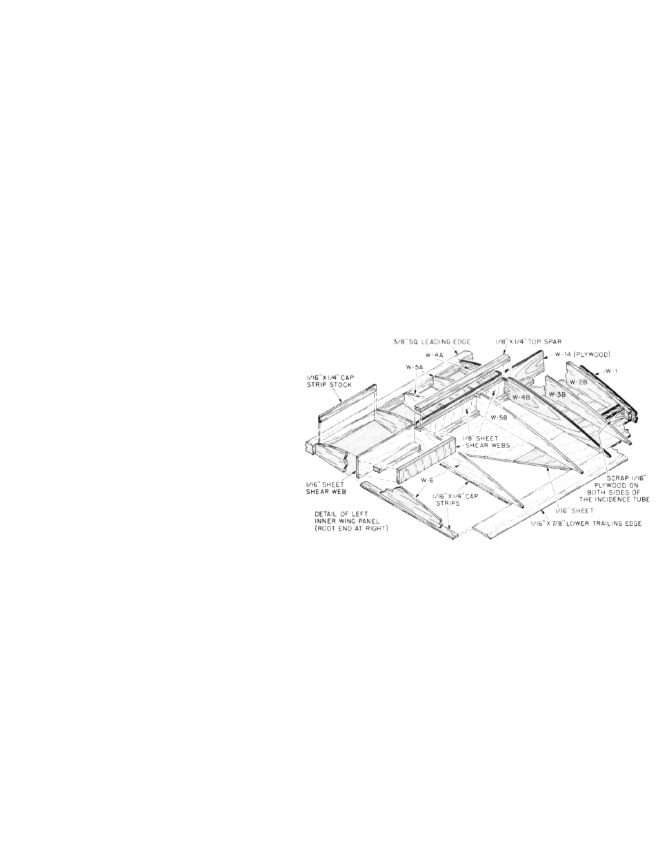
WING ASSEMBLY
Before starting this assembly sequence, you must make
the decision whether or not to build the spoiler option.
While the plans are sufficient in explaining the addition of
this option you should modify four (4) W-6 wing ribs by
relieving them to accept the 1/4" x 1" trailing edge stock,
which will be the spoilers. You will also note that the top
1/16" sheeting requirements are somewhat different and is
called out with —--— lines. Installation of the flexible
plastic dial chord housing tubes must be done before the
top, rear root section sheeting is installed. The spoiler
option shown on the plans has been used quite success-
fully on our prototypes and really makes the METRICK
quite "deadly" in the spot landing phase of your flights.
Note that the first phase of the wing construction is the
building of the two inboard wing sections, followed by
building and fitting the two outboard wing sections.
1. Start by removing all necessary die-cut parts from
their sheets—do this carefully, using an X-acto knife
as required. We have made a practice of stacking all
of the ribs together, in the order that they are used
and lightly sanding them to uniform shape with the
sanding block. Also be sure that the top and bottom
spar notches line-up, again using the X-acto knife if
needed. Next, prepare the 1/16" bottom leading edge
sheeting by cutting it exactly to size shown on plan—
note that unlike the top sheeting, the bottom sheet
extends from the rear of the bottom spar, forward to
the front of the 3/8" sq. leading edge. Use your metal
straight edge and knife to make the front and rear
edges straight and parallel. Pin the bottom leading
edge sheeting in place directly over the plans.
2. Cut, fit and pin the 1/16" bottom trailing edge sheet in
place over the plans. Use a pencil and a ruler to now
mark the locations of all the wing ribs—remember
that the bottom spar will cover up any marks that are
too close to the rear edge of the bottom leading edge
sheet, so make these marks further forward. Now
cut, carefully fit and glue the inboard bottom center
sheeting in place—again, use your straight edge to
achieve straight, gapless butt-joints.
3. Cut, fit and glue in place all of the bottom 1/16" x 1/4" cap
strips.
4. Cut, fit and glue the bottom 1/8" x 1/4" spruce spar in
place, lining it carefully up with the rear edge of the
bottom leading edge sheeting. Before pinning it in
place, use your straight edge to be sure it is straight
and accurately placed.
5. Use one of your W-6 "full chord" ribs as a spacer and
locate and glue the 3/8" sq. leading edge in place on
the bottom forward leading edge sheet. Be sure to
glue and pin the leading edge in place straight and
properly spaced.
6. When the leading edges have dried, remove all of the
pins from it and any you have in place back to the
spar. As shown on the plans, the bottom leading
edge sheeting, at the front has to be raised off of the
building surface by about 1/16" to conform to the
bottom forward shape of the wing ribs. As shown, we
did this by inserting some 1/16" sheet in place, deep
enough to achieve the proper curvature.
7. Glue W-7A and W-7B ribs in place at the outboard
end—note the 1/16" gap between these two ribs at the
spar to allow the installation of W-17 later on. Use a
triangle to be sure these ribs are at right angles to the
work surface. Moving inboard, glue all five W-6's in
place, again make sure they are at right angles with a
triangle.
8. Trial-fit ply brace W-14 in place—note the "to root"
arrow and the slight angle at that end. This means
that this part has to be oriented with the angled end
toward the fuselage. This part must fit onto the
bottom sheeting, against the forward face of the
bottom spar and terminate at the inboard edge of
W-2A, as shown. Glue W-14 in place making sure the
top edge of it will still accept the top spar to be
inserted later.
9. Glue the remaining forward partial ribs in place;
W-5A, W-4A, W-3A. Glue rear partial ribs W-5B and
W-4B (ply) in place.
10. Rear ply brace, W-15 is glued in place next. Like W-14,
this part has a "to root" arrow and an angle also and
must be oriented correctly. The installation of this
part is meant to create a "box" for the 1/4" I.D. brass
wing tubes. When gluing W-15 in place, use one of
these tubes as a "spacer" to ensure a good fit.
11. Glue rear partial rib W-3B in place.
12. Vs" balsa root ribs W-2A and W-2B are now glued in
place. Note that these ribs are slightly angled at the
top to match the two angles of W-14 and W-15 at the
root.
13. As shown on the plans, cut, fit and glue in place on
the rear face of the 3/8" sq. leading edge, the 1/16" x 1/4"
balsa "sheeting shelves", between each rib—see
cross-section.
8