Top Flite Metrick User Manual
Page 6
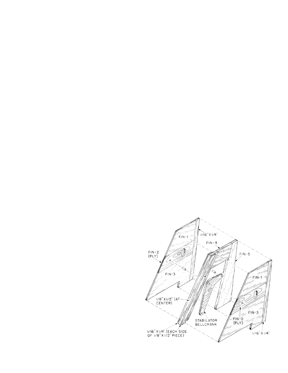
FIN AND BELLCRANK ASSEMBLY
1. Remove all required FIN parts from the die-cut
sheets; FIN #'s 1, 2 and 3 (two of each) and FIN #'s 4
and 5. Also carefully remove the BELLCRANK (3/32"
ply) using an X-acto knife as needed. Sand all edges
of the bellcrank and the surface until it is completely
smooth. Note on the plans that the bottom edge of
F-1 butts to the top edge of F-2 and the top edge of F-3
butts to the bottom edge of F-2; lightly sand these
edges to create a flat, gapless fit. Remove the oblong
die-cut from FIN-2's.
2. With a 1/8"dia. drill bit, drill-out the two required holes
at the top of the bellcrank for the 1/8" O.D. brass drive
tubes to be inserted—drill these holes at right angles
to the bellcrank. With a 1/16" dia. drill bit, drill-out the
two holes at the bottom of the bellcrank that will be
used for connection to the elevator servo. Lightly
sand-off any burrs.
3. Insert the forward 1/8" O.D. x 1/4" "pivot tube" and the
rear 1/8" O.D. x 1/4" "drive tube" into the holes at the
top of the bellcrank, center them so that an equal
amount of tubing is showing on each side of the
bellcrank. Making sure that these tubes are roughly
at right angles to the bellcrank, place a small amount
of Cyanoacrylate to the tube/ply joints to hold them in
place.
4. Assemble the 1/8" thick fin "core" directly over the
plans using the 1/8" x 1/2" balsa stock provided for the
leading edge and FIN #4 and 5. Glue a length of 1/16" x
1/4" balsa stock on top of the leading edge, flush with
the front edge of it.
5. On a flat work surface, make-up two fin "cover
assemblies" by edge gluing FIN #'s 1, 2 and 3
together. Holding these two assemblies together so
that they match as closely as possible, lightly sand
the leading and trailing edges with a sanding block to
get them as straight as possible and matched to one-
another.
6. Set one of the fin cover assemblies aside and glue the
other one directly to the fin core assembly, the lead-
ing edge against the 1/16" x 1/4" strip that was glued in
place earlier. Make sure this assembly is flat by pin-
ning it to the work surface. Glue another length of
1/16" x 1/4" balsa to the trailing edge of the exposed FIN
5 core and up against the cover assembly—allow to
dry.
7. Remove the fin assembly from the worksurface and
turn it over. Glue another 1/16" x 1/4" balsa strip to the
leading edge of the core as was done on the other
side. Fit in place, pin but do not glue, the remaining
fin cover assembly. Cut and fit the remaining 1/16" x 1/4"
balsa trailing edge strip that fits immediately behind
the fin cover—glue this in place and pin. Remember,
at this point the unglued fin cover is in place but
removeable.
8. Slip a scrap piece of 1/8" balsa inside the fin, from the
bottom, directly under the small indention on the
FIN-2 ply part (there is an arrow pointing to this).
Using a 1/8" dia. drill bit, drill a hole all the way through
the fin—NOTE, while a drill press is most useful here
it is not necessarily needed if reasonable care is taken
to drill this hole at as close to right angles as possible.
9. Remove the unglued fin cover assembly and the
scrap 1/8" balsa. Install the bellcrank into the fin by
pressing the forward "pivot" tube into the 1/8" dia.
hole you just drilled. You will note that the rear
"drive" tube is now free to move up and down in the
oblong hole. With the fin and bellcrank flat on the
work surface, you can now glue the remaining fin
cover assembly in place with the "pivot" tube
pressed through the hole in FIN-2—allow this
assembly to dry.
10. Using the sanding block, sand the sides of the com-
pleted fin as smooth as possible. Carefully cut-out
the 1/4" FIN-6 fairing. Lay the fin assembly over the
plans in the exact position shown and glue FIN-6 in
place on the leading edge of the fin. Set this assembly
aside for final sanding.
6