Top Flite Metrick User Manual
Page 7
RUDDER
1. Carefully cut-out rudder parts R-1, R-3, R-4 and R-5
from the printed 1/4" balsa sheet provided. Remove
plywood die-cut part R-2 from its sheet.
2. Position the completed fin and bellcrank assembly in
place on the plans and pin. Start rudder construction
by first cutting and pinning the 1/4" x 1/2" tailpost piece
in place about 1/32" away from the trailing edge of the
fin as shown. Next, fit R-1 in place with the bottom of
it about 1/32" away from the top of the fin—if neces-
sary, trim R-1 to fit as shown. Once satisfied with the
fit, glue R-1 in place. Remove the fin from the plans
and build the rest of the rudder as shown, pin and
allow to dry.
3. Using a single edge razor blade, relieve 1/16" of the
bottom tailpost area to accept ply part R-2 on the left
side only. R-2 should be fitted to rest flush with the
top surface of the rudder assembly. Once satisfied,
glue R-2 in place.
4. Sand the outside of the rudder to the shape shown on
the plans, followed by using the sanding block and
light sandpaper to sand each side smooth. As shown
in the drawing, bevel the leading edge of the tailpost,
where it will be hinged to the rudder, to facilitate free
left and right movement. Set the rudder aside for
final airfoiling.
STABILATOR ASSEMBLY
1. Carefully remove die-cut parts E-1 (1/8" balsa), E-2
(1/16"" balsa) and cut-out parts E-3 from 1/4" balsa sheet
which is printed. Note that the outside shapes of all of
the E-1's and E-2's should be identical—carefully and
accurately stack these parts together, pin and with a
sanding block, "match" all of their edges. This proce-
dure should produce a precise fit.
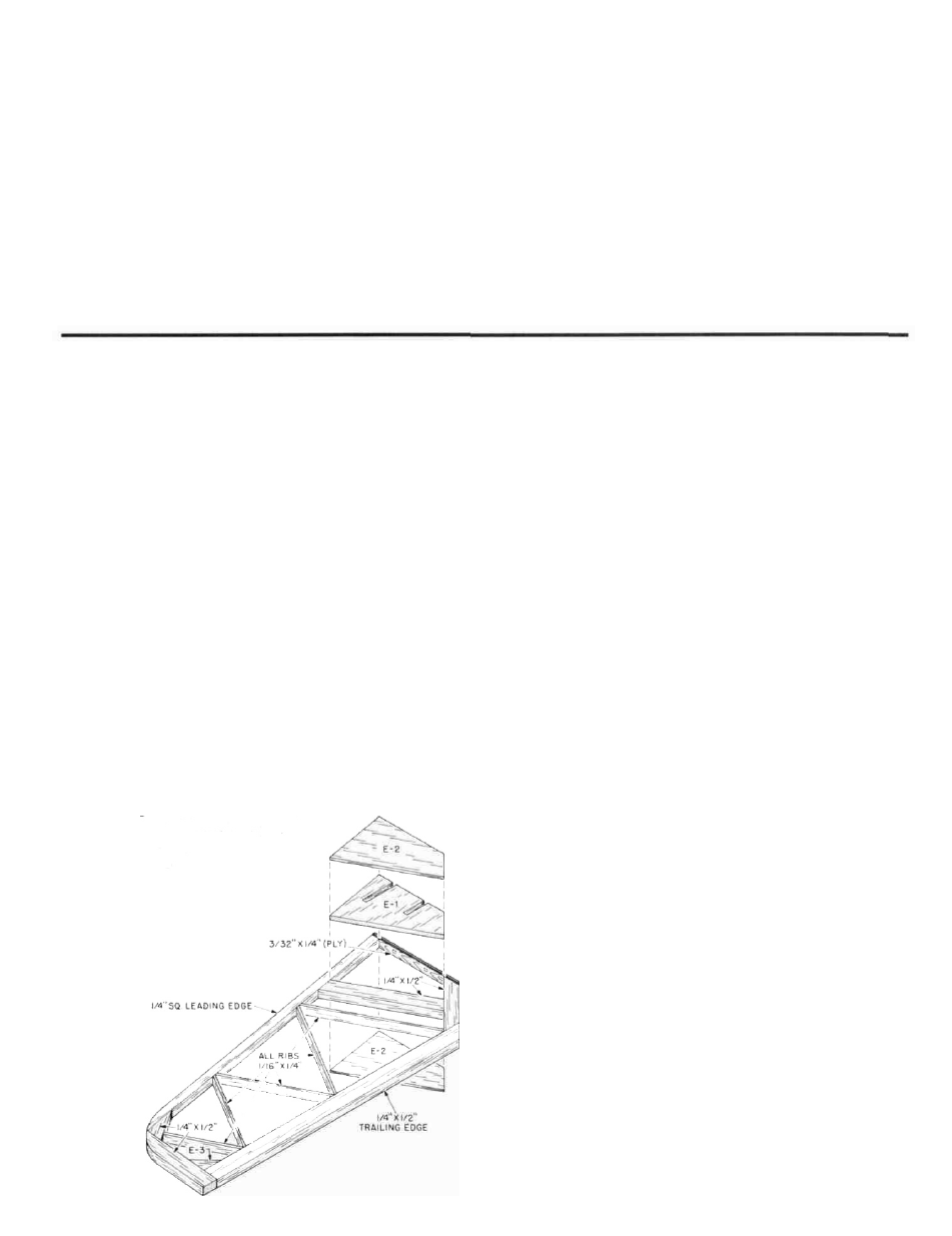
2. The stabilator halves will be built directly over the
plans and both halves will be built at the same time.
Start construction by accurately pinning E-2 in place
followed by cutting, gluing and pinning the 1/4" sq.
leading edge in place. Complete the stab outline by
cutting and gluing in place the remaining pieces of
1/4" x 1/2" balsa stock shown. Glue the 1/4" E-3 rear
gussets in place and cut the forward gussets from the
1/4" x 1/2" balsa provided and glue in place. Next, cut
and glue the 1/16"" x 1/4" diagonal "ribs" in place.
3. Now glue the slotted 1/8" balsa E-1 in place directly on
top of the bottom E-2. Pin in place and allow to dry.
4. From the 3/32" x 1/4" ply strip provided, cut two 3-3/32"
lengths. These will be used for the stab "cap roots."
As shown on the plans, use a sharp pencil, a ruler and
a triangle to locate the two positions for drilling the
stab roots with the two required
1/8" dia. holes. Again, when you
are drilling these holes, do so
at right angles.
5. Remove the stab halves from the plan and place one
half over the other so that they match as closely as
possible—pin together in this position and using the
sanding block, match their outlines including the
radiusing of the leading edge tips as shown on the
plans. Carefully sand the root sections flat. Unpin the
two stab halves. Glue the 3-3/32" ply root caps to the
stab roots, carefully matching the 1/8" dia. holes with
the tube slots in E-1—allow to dry before proceeding
to Step 6.
6. From the hardware package, remove; one (1) 3/32" dia.
x 2-5/8" wire; two (2)
3
3/32" I.D. x 1
3
3/16" brasstubes; one (1)
3/32" x 2" wire; two (2) 3/32" I.D. x 7/8" brass tubes.
You will need to use a slower drying epoxy, such as
15-minute to have the proper amount of time to do
the job right. You are now going to epoxy the forward
13/16" long stab pivot tubes and the rear 7/8" long stab
drive tubes in place through the holes drilled in the
3/32" ply stab roots and into the slots in E-1. Be very
careful to not get any adhesive in the tubes them-
selves. As soon as both forward tubes are in place, fill
the remaining area of the slots with epoxy and level it
with your finger. Repeat this process with the rear
tubes. Note that these tubes are flush with the 3/32" ply
stab roots. Insert the forward and rear wires into one
stab half and slip the other stab onto the wire ends
and lay this whole assembly directly over the
stabilator plan and pin accurately in place with the 1/4"
gap in the center, as shown. Now glue the remaining
E-2's in place directly over the E-1's and tubes—pin
and allow to dry completely.
7. Remove the stabs from the plan and trial-fit them to
the fin and bellcrank assembly. The fit we are looking
for is firm bordering on tight—not free or loose. The
firm fit retains the stab halves in place to the fin. On
one of our prototypes we made the components so
accurately that the fit was too free and we cured this
by smearing a thin film of 5-minute epoxy on the
wires and lightly sanding them until all fits were firm.
8. Using a sanding block and light sandpaper, sand the
top and bottom of the stabs until they are quite
smooth and set them aside for final airfoil sanding.
7