Apply the decals, Get the model ready to fly – Top Flite TOPA0970 User Manual
Page 27
27
(Continued from page 25)
❏
5. Glue the canopy to the fuselage using canopy
glue such as J&Z R/C 56 Canopy Glue (JOZR5007).
❏
6. This completes the assembly process!
APPLY THE DECALS
Use the following instructions to apply the decals.
❏
1. Be certain the model is clean and free from oily
fi ngerprints and dust. Prepare a dishpan or small
bucket with a mixture of liquid dish soap and warm
water—about one teaspoon of soap per gallon of
water. Submerse the decal in the soap and water
and peel off the paper backing.
Note:
Even though
the decals have a “sticky-back” and are not the water
transfer type, submersing them in soap & water
allows accurate positioning and reduces air bubbles
underneath.
❏
2. Position decal on the model where desired.
Holding the decal down, use a paper towel to wipe
most of the water away.
❏
3. Use a piece of soft balsa or something similar
to squeegee remaining water from under the decal.
Apply the rest of the decals the same way.
Refer to the pictures on the box to determine the
location for the decals.
GET THE MODEL READY TO FLY
CHECK THE CONTROL DIRECTIONS
❏
1. Turn on the transmitter and receiver and center
the trims. If necessary, remove the servo arms from
the servos and reposition them so they are centered.
Reinstall the screws that hold on the servo arms.
❏
2. With the transmitter and receiver still on, check
all the control surfaces to see if they are centered. If
necessary, adjust the clevises on the pushrods to
center the control surfaces.
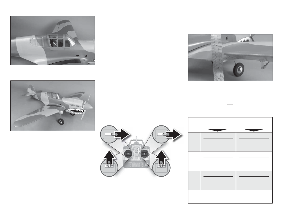
FULL
THROTTLE
RUDDER
MOVES
RIGHT
ELEVATOR
MOVES DOWN
RIGHT AILERON
MOVES UP
LEFT AILERON
MOVES DOWN
4-CHANNEL RADIO SETUP
(STANDARD MODE 2)
❏
3. Make certain that the control surfaces and the
carburetor respond in the correct direction as shown in
the diagram. If any of the controls respond in the wrong
direction, use the servo reversing in the transmitter to
reverse the servos connected to those controls. Be
certain the control surfaces have remained centered.
Adjust if necessary.
SET THE CONTROL THROWS
Use a Great Planes AccuThrow (or a ruler) to
accurately measure and set the control throw of each
control surface as indicated in the chart that follows. If
your radio does not have dual rates, we recommend
setting the throws at the
low
rate setting.
NOTE
: The throws are measured at the
widest part
of
the elevators, rudder and ailerons.
These are the recommended control surface throws:
ELEV
A
T
OR
HIGH RATE
LOW RATE
5/8"
[16 mm]
11°
Up
5/8"
[16 mm]
11°
Down
7/16"
[11mm]
7°
Up
7/16"
[11mm]
7°
Down
5/8"
[16mm]
14°
Up
5/8"
[16mm]
14°
Down
1/2"
[13 mm]
12°
Up
1/2"
[13 mm]
12°
Down
1-1/2"
[38mm]
32°
Full
Rate
3/4"
[19mm]
15°
1/2
Rate
1-1/2"
[38mm]
18°
Right
1-1/2"
[38mm]
18°
Left
1"
[25mm]
12°
Right
1"
[25mm]
12°
Left
R
UDDER
AILER
ONS
FLAPS