Top Flite TOPA0400 User Manual
Page 48
INSTALL THE
RUDDER PUSHROD
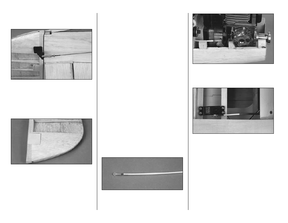
❏
1. Thread a 4-40 nut, a silicone retainer and
4-40 threaded clevis 14 turns onto the end of a
4-40 x 36" threaded pushrod. Attach a heavy-duty
control horn (not included) to the clevis and
position it on the rudder so that the clevis holes are
aligned with the hinge line. Mark the outline of the
rudder horn.
❏
2. Center the shaped 1/8" x 1" x 1" plywood
rudder horn base over the outline of the rudder
control horn. Mark the outline of the plywood
rudder base. Remove the balsa from inside the
outline of the rudder base until it is flush with the
side of the rudder.
❏
3. Drill four or five 1/8" diameter holes in the
balsa under the rudder base. This will provide
more gluing surface to hold the rudder base
securely to the rudder. Use 6-minute epoxy to glue
the base to the rudder, making sure to work epoxy
into the 1/8" holes.
❏
4. Reinstall the rudder, position the rudder
control horn on the rudder base and mark the
mounting hole locations. Depending on the type of
control horn used, drill the proper size pilot holes
at the marks and mount the control horn to the
rudder base with wood screws (not included).
❏
5. Center the rudder servo and the rudder.
Attach a solder clevis to the outermost hole in the
rudder servo arm. Cut the rudder pushrod to the
appropriate length. Remove the pushrod and the
solder clevis from the fuselage and slide a silicone
retainer on the pushrod. Solder the clevis to the
pushrod. Reinstall the pushrod and attach the
clevises to the servo arm and the control horn.
INSTALL THE
THROTTLE PUSHROD
The following throttle pushrod installation is for
the U.S. Engines 41cc. The same setup may
be used with other brands of engines with only
slight modification.
❏
1. Install the throttle servo in position on the
servo rails in front of former F-5.
❏
2. Thread the 2-56 x 1" threaded stud into the
nylon ball link. Thread this assembly 1/2" or
more into the end of the white nylon 36" inner
pushrod tube.
❏
3. Insert the inner pushrod into the throttle outer
pushrod tube. Install the pivot ball on the throttle
arm and secure it with a nut. Attach the ball link to
the pivot ball on the throttle.
❏
4. Attach the Screw-Lock Pushrod Connector
to the throttle servo arm. Slide a 2-56 x 4" threaded
pushrod through the pushrod connector and mark
the inner pushrod approximately 1/2" forward of the
threads. Cut the inner pushrod and thread the
2-56 x 4" threaded pushrod 1/2" into the inner
pushrod. Secure the pushrod in the screw-lock
pushrod connector with a 4-40 x 1/8" cap screw.
- 48 -