Installation – Toa PE-154BS User Manual
Page 3
Speaker cable
Mounting hanger
(accessory)
Screw terminal
COM (Gray)
HOT (Blue)
HOT (Brown)
(Earth)
COM (Black)
Screw terminal
3
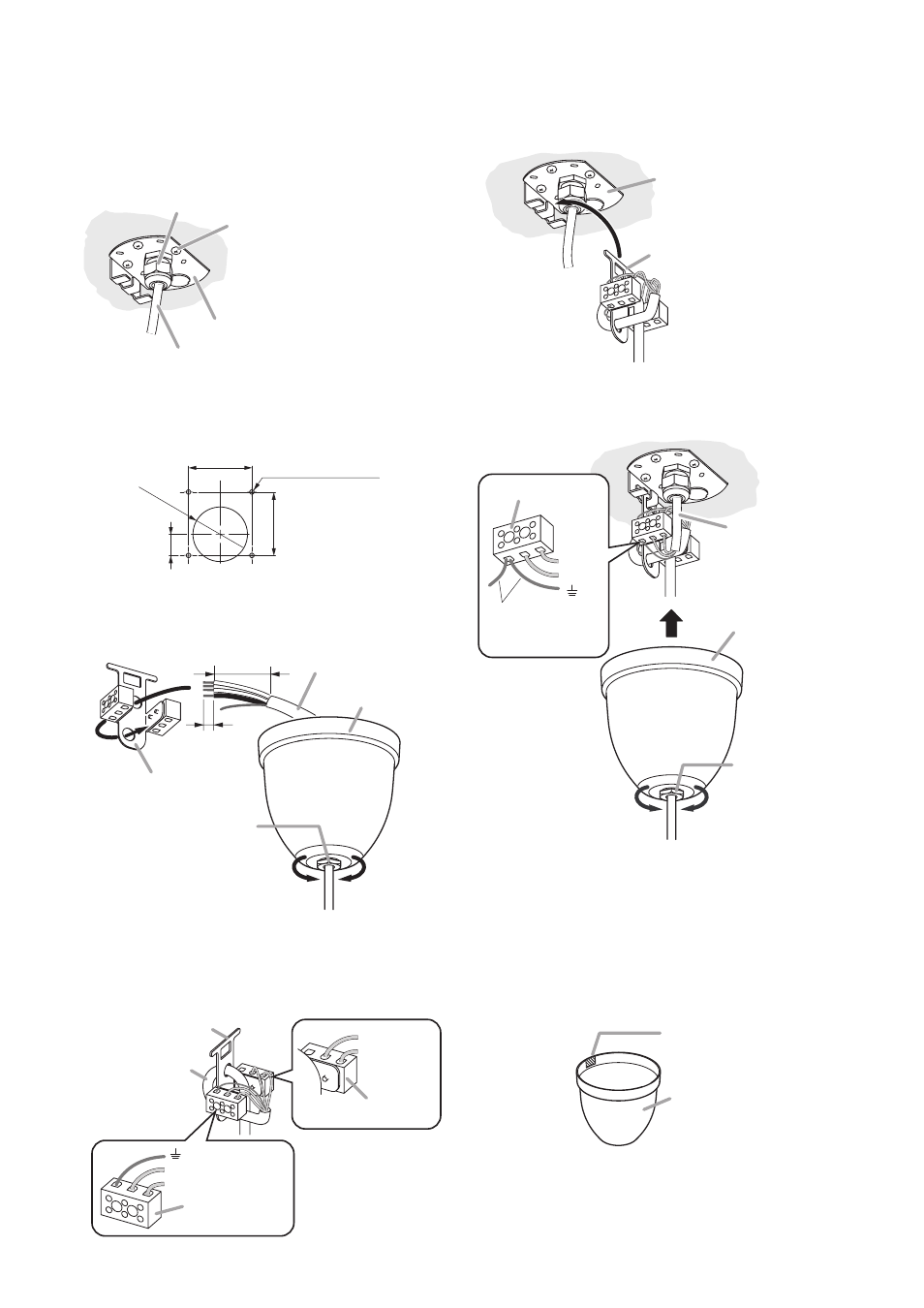
4. INSTALLATION
Step 2. Pass the speaker cable through the supplied
ceiling cover, and cut the cable to the
desired length.
Step 1. Secure the ceiling bracket to the ceiling with
4 screws.
Pull the cable through the cable gland in the
bracket.
Cable gland
Cable (from the amplifier)
Ceiling bracket (accessory)
Tapping screw 4 x 16 (accessory)
Note
If these screws are not appropriate
for the ceiling material, separately
prepare the proper screws.
Ceiling
Ceiling cover
(accessory)
Cover-retaining nut
Tightens
Loosens
8 mm
(0.31")
55 mm
(2.17")
Speaker cable
3 m (9.84 ft)
Mounting hanger
(accessory)
2
3
Step 4. Connect the speaker cable to the screw
terminal.
Mounting hanger
(accessory)
Ceiling bracket (accessory)
Step 5. Put the mounting hanger onto the ceiling
bracket's hook.
Step 6. Connect the cable (from the amplifier) to the
screw terminal.
Ceiling cover
Cover-retaining
nut
Tightens
Loosens
Cable (from the
amplifier)
HOT
COM
Screw terminal
6
7
Note
Connect 2 cables.
Step 7. Push the ceiling cover, slipped over the
connected cables, onto the ceiling surface,
then tighten the cover-retaining nut using a
17 mm (0.67") hex wrench.
In the case of exposed wiring, cut out the
cable entry tab on the rim of the cover, then
make connections.
Ceiling cover
Cut out this thin tab.
(another tab is on the
opposite side.)
Step 3. Run the speaker cable through the cable
holes in the mounting hanger.
ø31
(1.
22)
36 (1.42)
36 (1.42)
12
(0.47)
4-unthreaded hole
[Cable gland hole dimensions (Reference)]
Unit: mm (in)
Note: Make a clearance hole for the cable gland in
the ceiling panel as needed so that the ceiling
bracket can be attached firmly to the ceiling.