Installation, Connections, Input power (impedance) change – Toa BS-61WT-A User Manual
Page 2: Volume control, When mounting onto the speaker receptacle, When mounting using anchor bolts, Connection of the bs-61wa, Connection of the bs-61wt-a, Bs-61wa, Bs-61wt-a
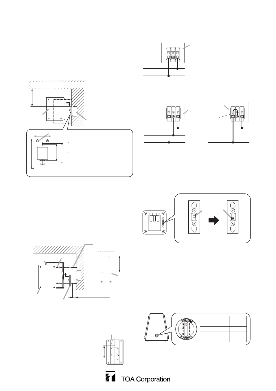
3. INSTALLATION
3.1. When Mounting onto the Speaker Receptacle
Step 1. Connect the speaker cable to the supplied
speaker receptacle. (See "Connections.")
Step 2. Install the speaker receptacle to an in-wall box
with the machine screws M4 x 35, or on the wall
with the tapping screws 4 x 35.
Step 3. Hold and slide the speaker to insert its speaker
plug into the speaker receptacle.
133-01-446-00
3.2. When Mounting Using Anchor Bolts
Step 1. Drive anchor bolts (not supplied) into the wall.
Step 2. Connect the speaker cable to the supplied
speaker receptacle. (See "Connections.")
Step 3. Slide the speaker receptacle to insert it into the
speaker plug.
Step 4. Remove the baffle on one side, and fix the unit
from the inside using nuts and washers.
Step 5. Replace the removed baffle.
Speaker
In-wall electrical box
Over 115 mm (4.53")
Precautions when installing the
speaker receptacle
Install the speaker receptacle
referring to its "UP" mark.
Position the receptacle at least
115 mm (4.53") away from the
ceiling or projection of a structure.
a = 70 mm (2.76")
c = 66.7 mm (2.63")
b = 120 mm (4.72") d = 83.5 mm (3.29")
UP
a
UP mark
c
d
b
Ceiling or projection of a structure
70 (2.76)
180
(7.09)
30 – 40 (1.18 – 1.57)
Baffle mounting
screw (4 pieces)
Speaker
Speaker
Nut and washers
Speaker receptacle
Unit: mm (in)
[Anchor bolt
mounting dimensions]
Anchor bolt (M6 - M8)
3.3. When Mounting to the Optional YS-31W
Suspension Bracket
Attach the YS-31W to the speaker
using 2 screws on the speaker's
rear panel.
For details, refer to the instruction
manual attached to the YS-31W.
(5.51")
140 mm
Speaker's rear panel
4. CONNECTIONS
4.1. Connection of the BS-61WA
Normal (N)
Common (COM)
Speaker receptacle's rear
(COM)
C
(HOT)
N
R
Normal (N)
Urgent (R)
Common (COM)
Speaker receptacle's
rear
Short
[3-wire system]
(COM)
C
(HOT)
N
R
Normal (N)
Common (COM)
[2-wire system]
(COM)
C
(HOT)
N
R
4.2. Connection of the BS-61WT-A
5. INPUT POWER (IMPEDANCE) CHANGE
5.1. BS-61WA
To change the input power (impedance), use the input
selector switch on the speaker's rear panel.
BS-61WA's
rear panel
L
H
6 W (1.7 kΩ) setting
2 W (5 kΩ) setting
(Factory preset)
Input selector
switch
H
L
H
L
5.2. BS-61WT-A
Inner wiring change is needed for the input power change.
So, consult your nearest TOA dealer.
6. VOLUME CONTROL
(BS-61WT-A ONLY)
Adjust the sound volume using the slide switch on the
speaker's bottom surface.
BS-61WT-A's
bottom surface
Switch position
Volume
3
High
2
Middle
1
Low
0
Off
URL: http://www.toa.jp/