Warning, Installation, Input connectors – Toa FB-150W User Manual
Page 3
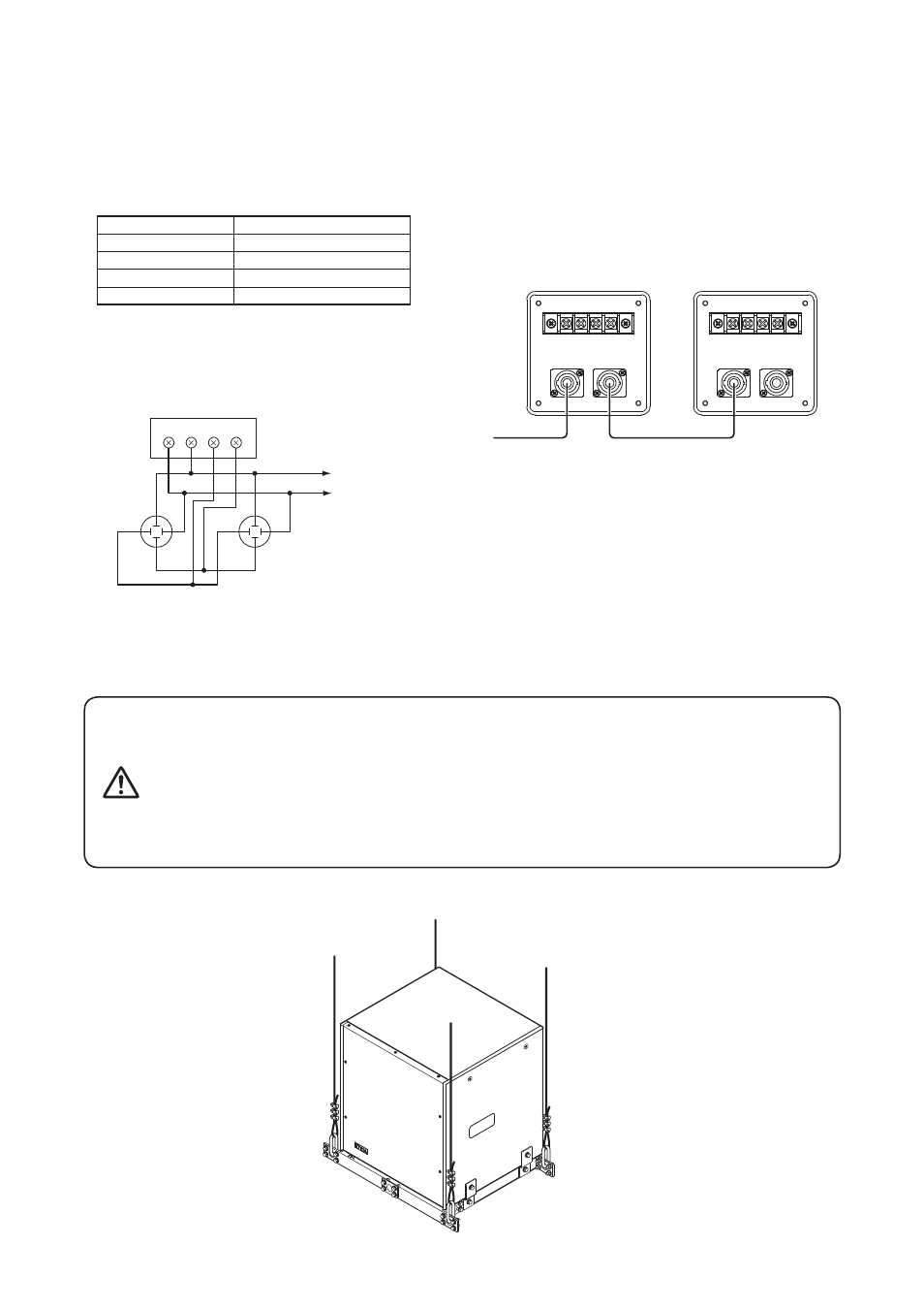
• The NEUTRIK Speakon connectors are internally
connected in parallel to the screw terminals; you can use
either one.
• The table below shows the pin arrangement of the
Speakon NL4MP connector.
Pin No.
FB-150B, FB-150W
1 +
Speaker +
1 -
Speaker -
2 +
-
2 -
-
• The usable connector (on the cable end) for the Speakon
NL4MP is Speakon NL4FC or NL4FX.
• Wiring diagram of the input connectors is shown below.
• Two Subwoofer Systems can be operated in parallel by
connecting them in a cascade configuration as shown
below.
Note
Be sure to connect the Subwoofer System to the power
amplifier's output terminal of 4 Ω or less.
Connecting it to an output terminal of over 4 Ω may cause
amplifier failure.
Screw terminal 4P
Speakon NL4MP x 2
2+
1–
2–
1+
2+
1–
2–
Speaker +
Speaker –
1+
1+
1–
2– 2+
First speaker
Second speaker
5. INSTALLATION
The Subwoofer System can be installed on the floor or can be suspended from a ceiling, etc. When suspending, use the
optional HY-PF7B or HY-PF7W Speaker Rigging Frame.
4. INPUT CONNECTORS
For installation method, refer to the instruction manual supplied the HY-PF7B or HY-PF7W.
• Use the suspension wires, chains, and anchor shackles that are
strong enough to withstand the total weight of the speaker and
mounting hardware.
Failure to do so may cause the speaker to fall, resulting in personal
injury.
• Owing to the unit's size and weight, be sure that at least two
persons are available to install the unit. Failure to do so could result
in personal injury.
wARNING