Impedance detection module vx-200sz-2, Side] [front – Toa VX-200SZ-2 User Manual
Page 7
7
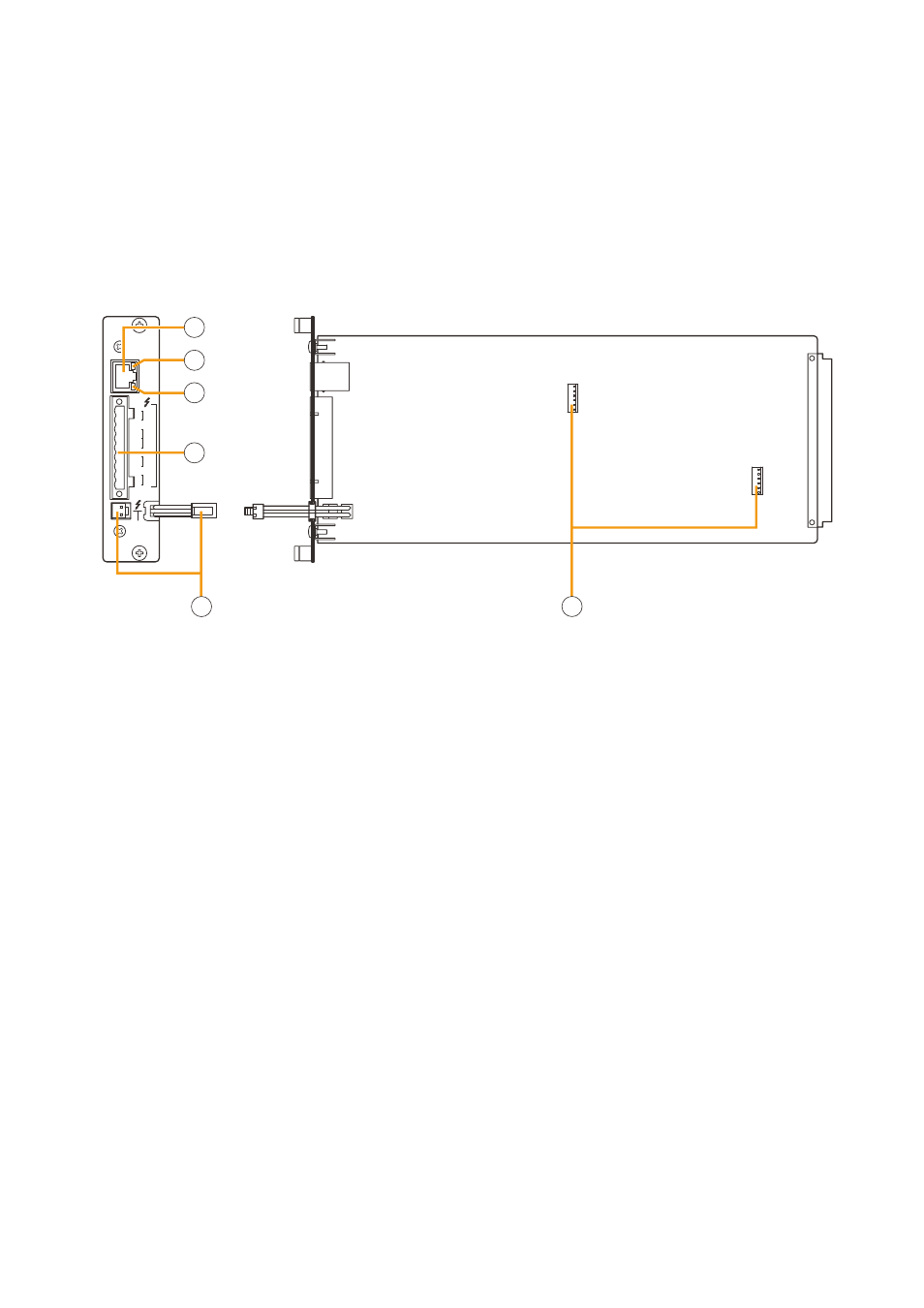
4.2. Impedance Detection Module VX-200SZ-2
STANDBY
PA BUS
PA
LINK
A
B
H
SP
OU
T
C
H
SP
OU
T
AB
C
H
PA
IN
C
N1
N2
C
AT
T
CTRL
VX-200SZ-2
[Side]
[Front]
3
4
5
6
1
2
1. Power amplifier link connector [PA LINK]
This RJ45 connector connects to the PA LINK
connector of the VP-200VX Power Amplifier Input
module or the VP-3000 series Power Amplifier.
2. Speaker line A status indicator [A]
Shows the status of speaker line connected to the
SP OUT A terminal.
For details, refer to
.
3. Speaker line B status indicator [B]
Shows the status of speaker line connected to the
SP OUT B terminal.
For details, refer to
.
4. VX-200SZ plug-in screw connector
Signal lines to be connected are shown below:
• External attenuator control [ATT CTRL]
Permits connection of 4-wire system attenuators.
For the connection instructions, refer to
The attenuator bypass method can be changed
from relay to photocoupler type. For the
modification instructions, refer to
• Speaker outputs A and B [SP OUT A, SP OUT B]
Connect the speakers.
• Power amplifier input [PA IN]
Connects to the power amplifier's speaker
output.
5. Standby amplifier bus connector
[STANDBy PA BUS]
Connects to all outputs of a single VX-2000SF unit
to be switched over to the standby amplifier when
the power amplifier fails.
For details, refer to the VX-2000 series Instruction
manual.
6. VX-200SE mounting connector
Used to mount the VX-200SE Equaliser card.
Install this module in the VX-2000SF Surveillance Frame to detect speaker line short circuits, open circuits by
comparing impedance readings, and ground fault.
Please equate this module with the VX-200SZ when setting it on the PC software.
Important Note
When combining this module with the VP-200VX BGM Input Module, then the signal level applied to the VP-
200VX's external input should be low, i.e. about 10 dB below the rated level. The level can also be reduced by
the volume adjustment.