Block diagram, Pilot tone detection module vx-200sp-2, End-of-line unit – Toa VX-200SZ-2 User Manual
Page 20
20
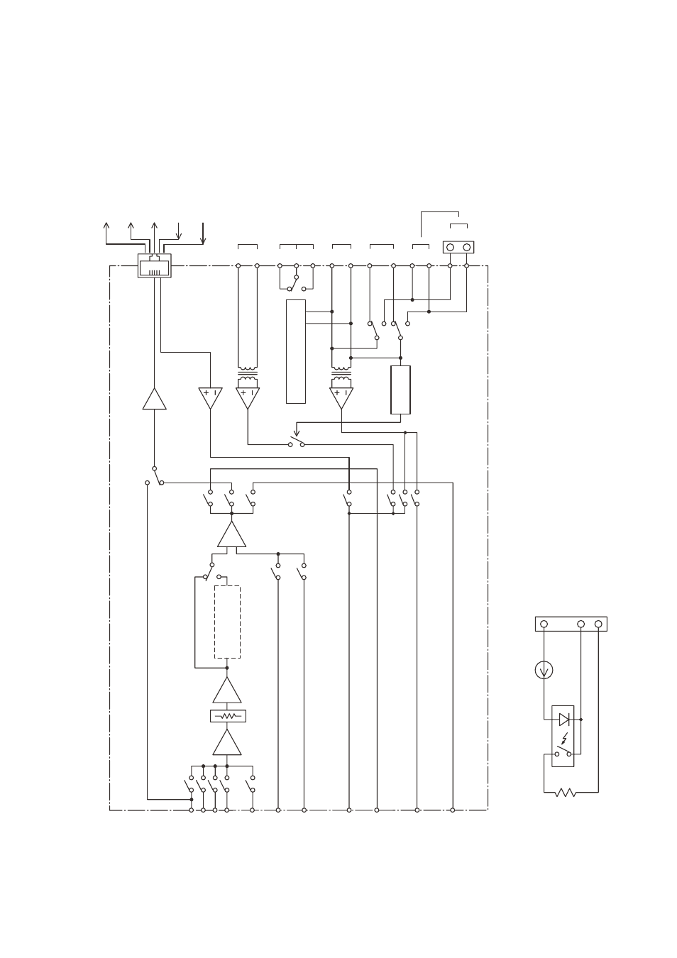
11.1. Pilot Tone Detection Module VX-200SP-2
Overheat Status Input
DC Fuse Blowout Detection Input
Standby Control Output
Audio Signal Output (balanced)
Audio Monitor Output (balanced)
Speaker Output [SP OUT]
Power Amplifier Input [PA IN]
External Attenuator Control
Line Monitor Input [LINE MONITOR]
Power Amplifier Link Connector [PA LINK]
Standby amplifier Bus Connector [STANDBY PA BUS]
Detection
*
Ground Fault Detection
SA2
LA
RM-200XF's CPU SW
OFF
ON
Equaliser Card VX-200SE
OPTION
SA1
Audio Bus
1
Audio Bus
2
Audio Bus
3
Audio Bus
4
Pilot Tone Bus
1
40 kHz
Pilot Tone Bus
2
20 kHz
Pilot Tone Monitor Bus 1 (20 kHz)
Pilot Tone Monitor Bus 2 (40 kHz)
Standby Amplifier Bus
PhotoMOS RELAY
[End-of-line unit]
Pilot Tone Bus
3
40 Hz
Audio Monitor Bus
BA
[ATT CTRL
]
H
C
H
C
C
H
H
N1
C
N2
C
H
C
H
C
E
Controls the switch pointed by an arrow with the voltage difference between the speaker line and the equipment chassis.
*
11. BLOCK DIAGrAM