Nomenclature and functions – Toa DP-L2 v.2.00 User Manual
Page 6
6
1
2
3
4
5
6
7
8
9
10
11
12
13
14
15
16
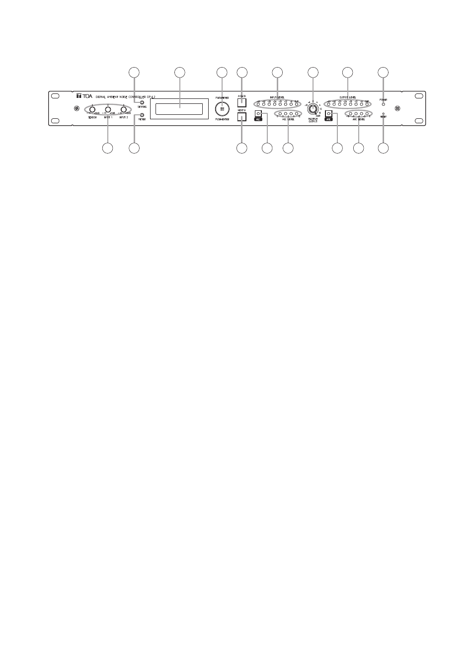
5. NOMENCLATURE AND FUNCTIONS
[Front]
1. Power indicator
Lights when the power is switched on.
Tip: The power switch (17) is located on the rear
panel.
2. Sensitivity controls
Adjust the input sensitivity for SENSOR input,
INPUT 1, and INPUT 2.
Factory-setting: 0 dB (center position).
3. SETTING key
Used to set each function. If this key is pressed,
the setting screen is displayed on the LCD screen.
4. METER indication selector key
Indications of channels for which the signal level is
displayed cycle through S (SENSOR level), 1
(Channel 1), and 2 (Channel 2) with each
depression of this key. (See p. 14.)
5. Liquid crystal display
Pressing each function key displays the
corresponding setting screen on this display.
If any key is not used for a specified period of time
while the setting screen is displayed, the ALC and
ANC levels are displayed.
6. PARAMETER/PUSH-ENTER knob
Rotate this knob to change parameters or select
the setting contents on the setting screen.
(Such parameters and setting contents changed
with this knob begin to work in real time.)
To save the current parameters, press this knob
while the setting screen is displayed.
Note
If not saved, newly set parameters are cancelled
when the power is switched off or the RESET key
is pressed. Pressing this knob when the PUSH
ENTER indication is displayed validates the on-
screen setting item and saves the current
parameters.
7. BACK key
Returns the setting item display to a previous
screen.
8. NEXT key
Advances the setting item display to a next
screen.
9. ALC key
Permits the ALC function to be set to ON or OFF
by means of the PARAMETER knob (6). If both
this key and the SETTING key (3) are
simultaneously pressed, settings for the ALC
function can be performed.
10. INPUT LEVEL indicator
Indicates the input signal level of the channel
selected with the METER indication selector key
(4). (See p. 14.)
11. ALC LEVEL indicator
Indicates the amount of gain controlled by the
ALC function.
12. MAXIMUM OUTPUT level control
Sets the maximum output level if rotated.
13. ANC key
Permits the ANC function to be set to ON or OFF
by means of the PARAMETER knob (6). If both
this key and the SETTING key (3) are
simultaneously pressed, settings for the ANC
function can be performed.
14. OUTPUT LEVEL indicator
Indicates the output signal level of the channel
selected with the METER indication selector key
(4). (See p. 14.)
15. ANC LEVEL indicator
Indicates the amount of gain controlled by the
ANC function.
16. RESET key
Reactivates the unit.
Tip: Each set data stays stored, and is not
erased.