Toa DP-L2 v.2.00 User Manual
Page 15
15
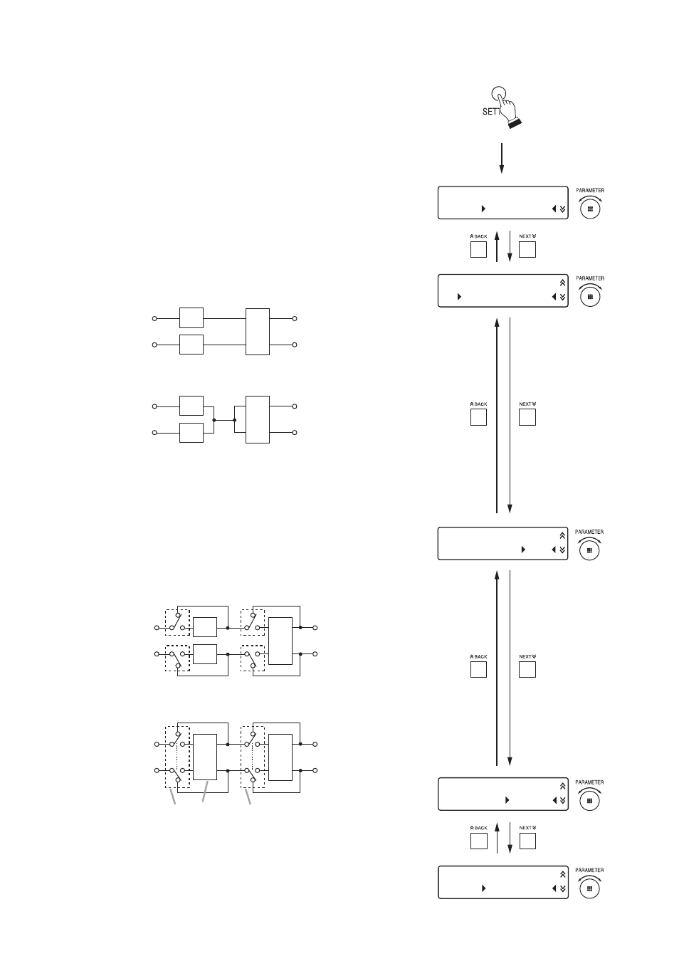
S E T T I N G
M O D E
N O R M A L
S U M M I N G
M O D E
O F F
C H A N N E L
L I N K
O F F
S E N S O R
S E N S E
+ 4 d B
S E N S O R
F I L T E R
A
W E I G H T
[Enter the setting screen.]
INPUT1
OUTPUT1
OUTPUT2
INPUT2
ALC
ALC
ANC
INPUT1
OUTPUT1
OUTPUT2
INPUT2
ALC
ANC
ALC
[SUMMING mode: OFF] (at CHANNEL LINK: OFF)
[SUMMING mode: ON (OUT=CH1+CH2) ] (at CHANNEL LINK: ON)
Step 1. Perform system settings.
Press the SETTING key to enter the system setting screen
(adjustment mode), then select the setting item with the
PARAMETER knob. (See p. 10; System setting flow chart.)
1-1. Set the adjustment mode.
Setting parameter: NORMAL or ADVANCED
The ADVANCED mode has more manually-operated setting
items than the NORMAL mode, enabling fine settings.
1-2. Set the SUMMING mode.
Setting parameter: OFF or OUT = CH1+CH2
The diagrams below show the relationship between the
input/output and the ALC/ANC functions when the
SUMMING mode is ON (OUT = CH1+CH2) and that when
the SUMMING mode is OFF.
1-3. Set the CHANNEL LINK.
Setting parameter: ON or OFF
Setting the CHANNEL LINK to ON permits both CH1 and
CH2 to be linked for each ON/OFF setting of the ALC and
ANC functions.
In this case, the input levels on CH1 and CH2 are ALC-
controlled at the same level.
INPUT1
ALC CH1's switch
ANC CH1's switch
ALC CH2's switch
ANC CH2's switch
OUTPUT1
OUTPUT2
INPUT2
ALC
ANC
ALC
INPUT1
OUTPUT1
OUTPUT2
INPUT2
LINK
ALC
ANC
LINK
[CHANNEL LINK: OFF] (at SUMMING mode: OFF)
[CHANNEL LINK: ON] (at SUMMING mode: OFF)
1-4. Set the SENSOR input sensitivity.
Setting parameter: +4 dB or –48 dB
1-5. Set the SENSOR input characteristics.
Setting parameter: A WEIGHT (A-weighted filter) or FLAT