Setting procedures – Toa DP-L2 v.2.00 User Manual
Page 14
14
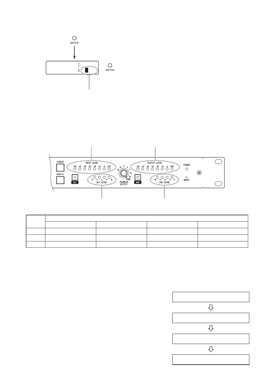
6.2.5. INPUT LEVEL, OUTPUT LEVEL, and ALC LEVEL indication selection
INPUT LEVEL indicator
OUTPUT LEVEL indicator
ALC LEVEL indicator
ANC LEVEL indicator
Selected
channel
Indicators
INPUT LEVEL indicator
S
1
2
SENSOR level
Channel 1 level
Channel 2 level
ALC LEVEL indicator
Channel 1
Channel 1
Channel 2
ANC LEVEL indicator
Channel 1
Channel 1
Channel 2
OUTPUT LEVEL indicator
MONITOR OUT level
Channel 1 level
Channel 2 level
A L C 1
O F F
M E T E R
A N C 1
0 d B
S
1 2
The cursor moves to the channels S, 1, 2, S, and so on for selection with each
depression of the METER indication selector key.
[Level indicators and indicated channel table]
6.3. Setting Procedures
The general outlines of setting procedures are as shown at right.
If there is a function that is not used, advance to the next procedure
without setting such a function. Ensure that equipment connections
are completed before performing each setting.
Note
Pressing the PUSH-ENTER knob during the setting saves the
current parameters. (Even if the unit's power is switched off and on
again, the set parameters are maintained.)
1. Perform system settings.
2. Set the maximum output level.
3. Set the ALC function.
4. Set the ANC function.