Connections of multiple remote control units, Wiring diagram of integrated remote control unit, Jp-0410 front-mounted upper row terminal block – Toa FS-971 SERIES User Manual
Page 8
8
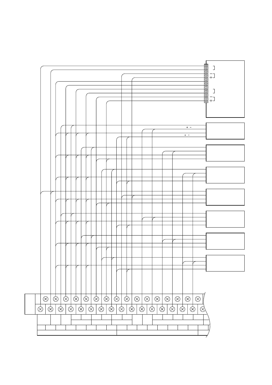
2.4. Connections of Multiple Remote Control Units
• Wiring diagram of Integrated Remote Control Unit
C
H
Others
RM BUS ( / )
24 VDC ( / )
REMOTE OUT (H / C)
C
H
REMOTE OUT
RM BUS
EMG ACTI
CPU CTRL OFF
MONITOR
24 VDC
Eighth remote
control unit
First remote
control unit
Third remote
control unit
Fourth remote
control unit
Fifth remote
control unit
Sixth remote
control unit
Seventh remote
control unit
Second remote
control unit
EF
(FA)
EMG
ACTI
CPU
OFF
C
H
GND
24V
GND
24V
BATT 1 BATT 2 CHECK GND
MONITOR
1 EMG RM 24V 2 EMG RM 24V
DS CHECK
C1
H1
C2
H2
C3
H3
C4
H4
(-)1
(+)1
(-)2
(+)2
(-)3
(+)3
(-)4
(+)4
GND
EMG REMOTE BUS
EMG REMOTE AUDIO IN
JP-0410 front-mounted upper row terminal block