Connection method – Toa FS-971 SERIES User Manual
Page 5
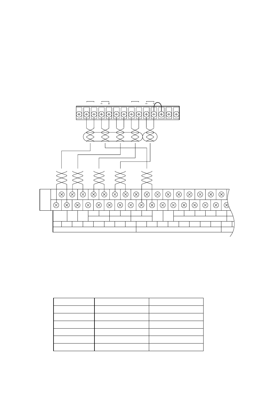
Control cable (4 pairs)
Under 50
Ω
Under 50
Ω
Under 50
Ω
Under 50
Ω
Under 50
Ω
Under 50
Ω
5
2. CONNECTIONS OF INTEGRATED REMOTE CONTROL UNIT RM-971
2.1. Connection Method
• Use heat-resistant, shielded twisted-paired cables for connection.
• Connect between the front-mounted terminal block of Junction Panel JP-0410 and the terminal block of the
remote control unit.
2.2. Notes on Connections
The maximum cable distance between the main rack and the remote control unit is 800 m, and there is a
limitation to the cable length depending on the type and zone numbers of the connected remote control unit.
2.2.1. Maximum line resistance
EF
(FA)
EMG
ACTI
CPU
OFF
C
H
GND
24V
GND
24V
BATT 1 BATT 2 CHECK GND
MONITOR
1 EMG RM 24V 2 EMG RM 24V
DS CHECK
C1
H1
C2
H2
C3
H3
C4
H4
(-)1
(+)1
(-)2
(+)2
(-)3
(+)3
(-)4
(+)4
GND
EMG REMOTE BUS
EMG REMOTE AUDIO IN
REMOTE OUT
C
H
C
H
RM BUS
EMG
ACTI
CPU
CTRL OFF
MONITOR
24 VDC
POWER GND
JP-0410 front-mounted upper row terminal block
Remote control unit's terminal block
Control line
Power supply line
No. of zones
10 zones
20 zones
30 zones
40 zones
50-90 zones
Over 100 zones
Power cable (1 pair)
Under 5
Ω
Under 3
Ω
Under 2.5
Ω
Under 1.5
Ω
Under 1
Ω
Under 0.5
Ω