Toa FS-971 SERIES User Manual
Page 42
42
0
1
2
3
4
5 6
7
8
9
A
B
C
D
E
F
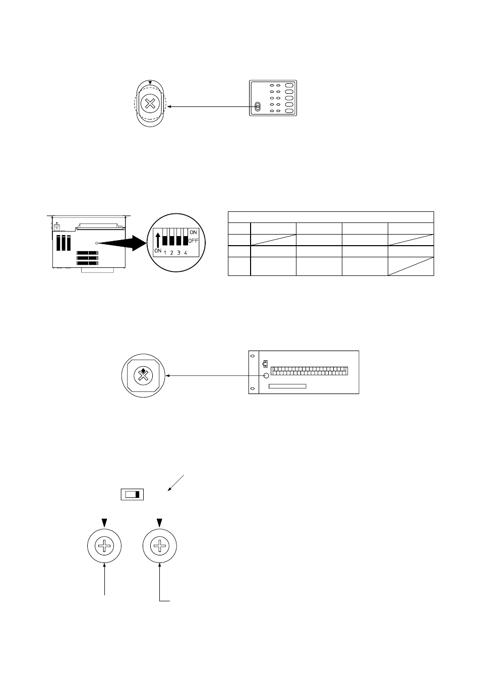
Address switch
4
Always OFF
3
24 V not output
24 V output
Emergency
24 V
2
Normal
Emergency
Emergency
contact
1
Always OFF
Test mode
ON
OFF
SW1 setting function
JP-0410 top panel
0
1
2
3
4
5 6
7
8
9
A
B
C
D
E
F
Address switch
0
1
2
3
4
5 6
7
8
9
A
B
C
D
E
F
0
1
2
3
4
5 6
7
8
9
A
B
C
D
E
F
Control mode switch: Set this switch to the AUTO position.
CONTROL SW
MANUAL
AUTO
ADDRESS
SWITCHING TIME
Address switch
Cannot be used when the control mode switch is in the AUTO position.
9.5.2. Expansion Control Panels EP-029-10 and EP-029-20
9.5.3. Junction Panel JP-0410
9.5.4. Expansion Junction Panels JP-039-10 and JP-039-20
9.5.5. Input Matrix Panel IM-011