Toa FS-971 SERIES User Manual
Page 16
16
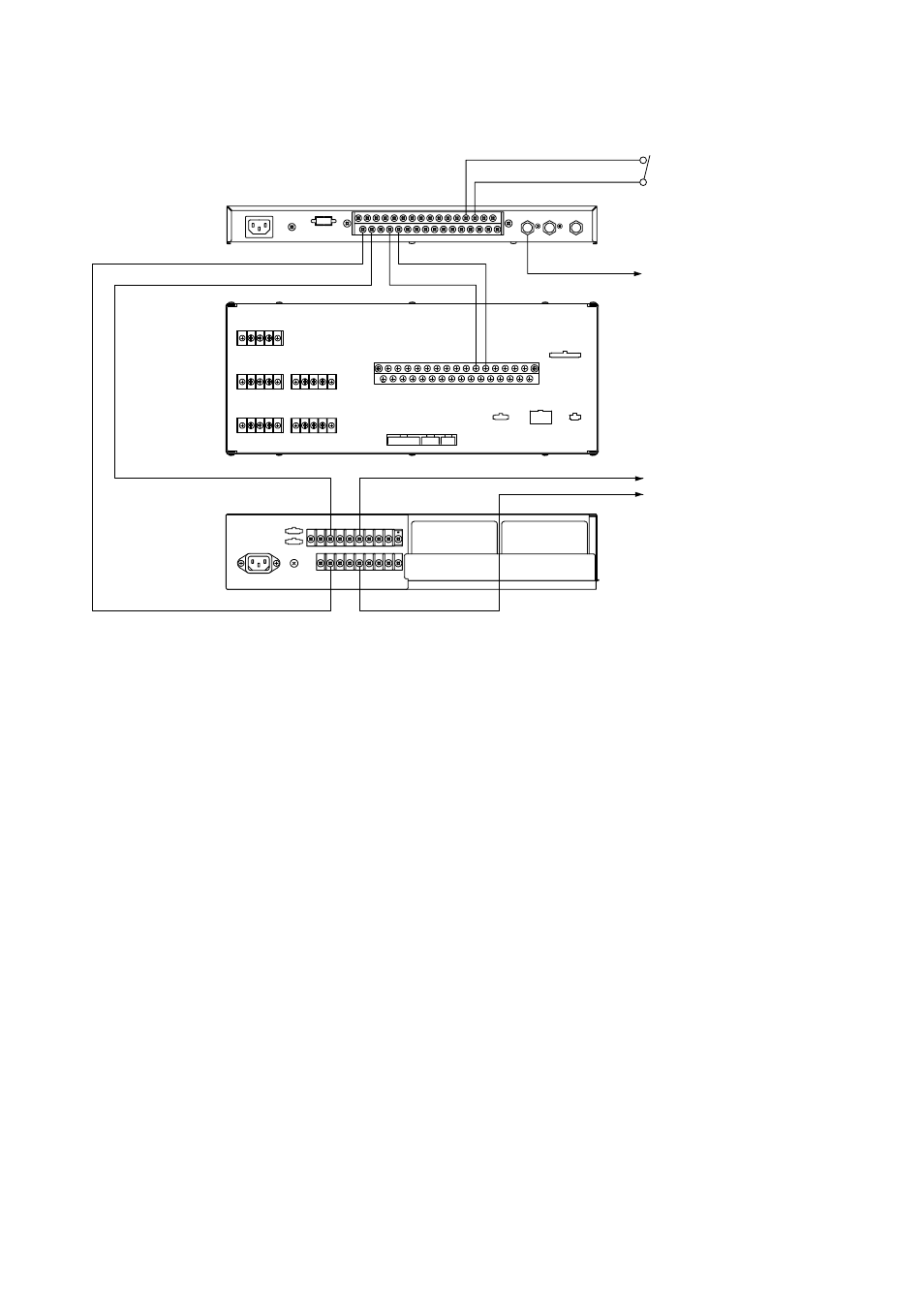
In Connection diagram 2, attenuator-free broadcast can automatically be made using the digital
announcement machine, etc. when the attenuator-free broadcast switch is shorted. Determine broadcasting
lines by writing into the Integrated Control Panel EP-0510.
Notes
• In this connection example, because power (24 VDC) is always supplied from the battery built in the
emergency power supply panel for power-failure general/attenuator-free broadcasts to the digital announcer,
etc. (even when the attenuator-free broadcast switch is not shorted), the battery is drained quicker than in
the example of Connection diagram 1. Use the battery having a sufficient current capacity.
• The power-failure broadcast function is operated even when the AC power is supplied. In such cases, the
power-failure broadcast takes precedence over all other broadcasts.
When the AC power is supplied, 24 VDC is not output from the emergency power supply panel's control
terminal.
• To automatically inspect the battery for power-failure general/attenuator-free broadcasts, connect the battery
check terminal and VOLT DOWN terminal in the same manner as the emergency power supply panel.
This applies to both connection examples of Connection diagrams 1 and 2.
Attenuator-free
broadcast switch
Attenuator-free input
24 VDC
(+)
(-)
Busy output
Output
Digital announcer, etc.
JP-0410
To EP-0510 attenuator-free
broadcast input
Emergency power supply panel for power-failure
general broadcast/attenuator-free broadcast
Connection diagram 2
To power amplifier 24 VDC