Tie Down G5 User Manual
Page 5
4
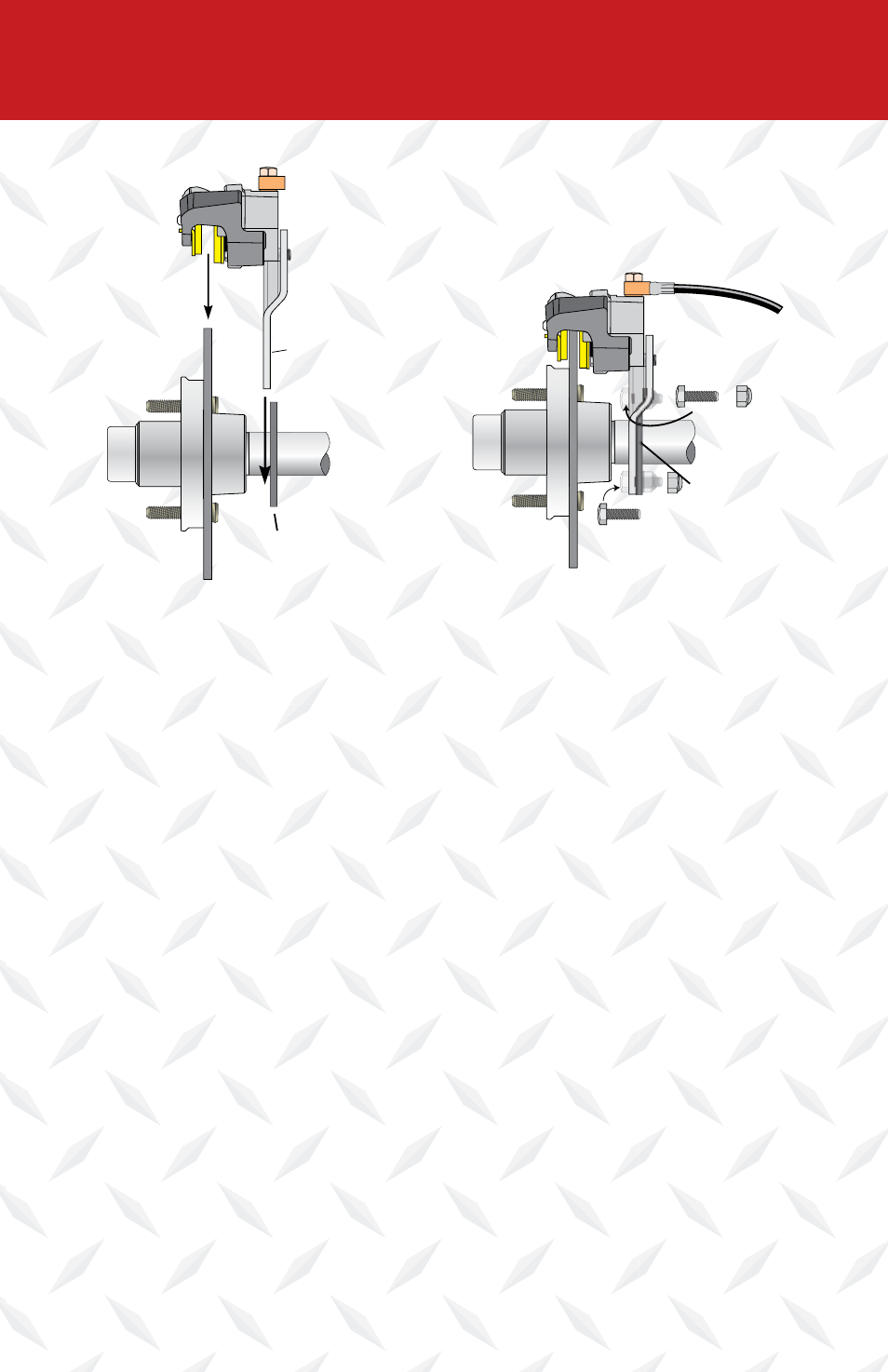
Bolt & Nyloc Nut
Bolt &
Nyloc Nut
Brake
Flange
Rotor/Hub
Caliper
Brake
Flange
Caliper
Mounting
Bracket
Mounting
Bracket
Slider Pin
Brake Line
Bolt & Nyloc Nut
Bolt &
Nyloc Nut
Brake
Flange
Rotor/Hub
Caliper
Brake
Flange
Caliper
Mounting
Bracket
Mounting
Bracket
Slider Pin
Brake Line
Slide caliper/mounting bracket
over rotor
Bolt mounting bracket to the
brake flange
10. Slide the assembled caliper onto the slider pins. Attach the assembled mounting
plate to the brake flanges on the axle, after sliding the caliper over the stainless
steel rotor. Preferred positions are 12:00, 9:00 and 3:00 “o-clock” or to the
backside. The brake flange will determine the exact positioning. Use 7/16”x 1-1/4”
zinc hex bolts, lock nuts/washers and torque to 40 ft. lbs.
11. Replace grease cap.
12. Caliper has a swivel inlet connector for the brake hose and a stainless steel bleeder
valve. The bleeder valve should have the top or highest position on the caliper.
Position the swivel brake connector so that the brake line easily connects to the
caliper. Tighten the bolt on the swivel connector to 20 ft. lbs.
13. Connect the flexible brake line to the swivel connector.
14. Repeat this assembly for the other wheels.
15. Install tire/wheel assembly(s), tighten wheel nuts to Trailer manufacturer or wheel
manufacture’s specifications. Test wheel for excessive tightness or excessive play.
Re-tension spindle nut if necessary.
16. Bleed brakes according to the trailer actuator’s instructions.
17. Road test vehicle in a safe place before traveling on main roads in traffic.
VERY IMPORTANT,
RE-CHECK LUG NUTS FOR PROPER TORQUE AFTER 25 MILES OF USE.