Pressure gauge tube assembly, 744e sprayer control – TeeJet 744E SPRAYER CONTROL User Manual
Page 13
9
744E Sprayer Control
98-70030 R0
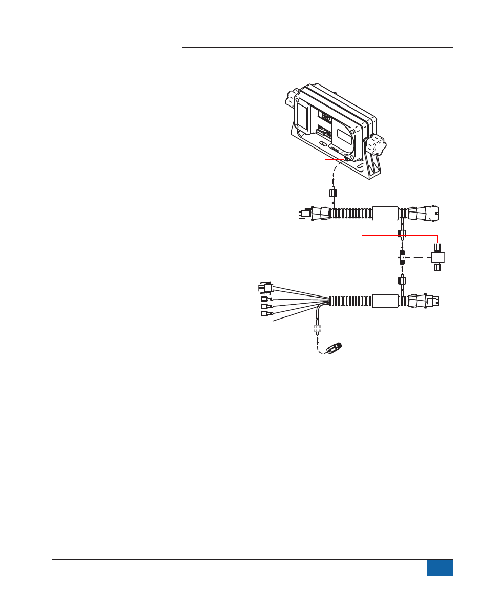
Pressure Gauge Tube Assembly
1. Determine the location at which the coupler is to be
installed. Cut the tubing at that point.
2. Remove the tube nuts from the 3 couplers and
slide the tubing through the nuts. The threaded
portion of the nut should face their respective
couplings. The tube should protrude approximately
½″ (1 cm) beyond the nut.
3. One brass tube insert is provided. This must be
used with the gauge coupling assembly.
4. Fluid leakage around the gauge indicates a poor
connection or a defective gauge.
NOTE: All cables and tubes must be placed in a way,
so that they cannot be snagged or pulled with
the operator’s feet. Tubes and cables must be
routed around sharp metal objects, edges and
moving parts with enough slack so that they
will not be pulled apart when sharp turns are
made.
Figure 2-2: Pressure gauge tube assembly
21720-8
DC: XX /XX
45- 20091
45- 20090
DC:XX/XX
744E Sprayer control
Harness
Harness
Optional isolator kit
Tube insert
Tube nut
Tube insert
Gauge elbow
Tube coupling
Tube nut
Tube nut
Tube nut
Tube insert
Tube insert