Installation instructions, Wire size: minimum wire gauge, Model (v/c) – Specialty Concepts ASC User Manual
Page 6: Battery connection, Solar array connection
INSTALLATION INSTRUCTIONS:
1. LOCATION / MOUNTING: - The ASC may be mounted in almost any indoor or outdoor
location. The unit should be mounted as close as possible to the batteries to avoid errors in
battery voltage reading. The ASC may be mounted on the rear of the solar panels using
outdoor-type double-stick foam tape. On units with temperature compensation (Option-A), the
ASC should be mounted within 10 feet (3m) of the batteries to enable the sensor cable to
reach the battery.
2. PROTECTION REQUIREMENTS: - The circuitry of the ASC is encased within hard epoxy
resin that offers substantial protection from the environment.
•
HEAT: - The unit should not be mounted in direct sunlight or close to any heat generating
source to avoid extreme temperature increases. The rear of the unit should not be blocked to
allow air flow for adequate cooling.
•
CORROSION: - The exposed terminal block is made of corrosion resistant nickel plated
brass. This will endure most outdoor environments. When the ASC is in an excessively
corrosive location, a coating of an oxide inhibitor should be applied to the terminals.
•
TEMPERATURE COMPENSATION CABLE (for units with Option-A): - The optional
sensor and cable need to be protected from damage (cuts, impacts, rodents). If the sensor
or cable is damaged, the ASC will not operate. (Refer to Options section: OPTION - A)
3. SELECT WIRE:
WIRE TYPE: - When possible, use stranded wire rather than solid wire. Stranded wire is less
likely to fail and cause loose connections over time. Consider using wires of different colors
to indicate source or polarity. Also, select a wire that offers the appropriate insulation for the
condition of the location. (Refer to the U.S. National Electrical Code)
WIRE SIZE: - Select wire of sufficient gauge to safely handle the rated current of the system
and to limit voltage drop. The ASC terminals accept up to 10 gauge stranded bare wire (and
12 gauge solid wire). (When using 10 gauge stranded wire, divide the end wires into two
equal sections and straddle the terminal screw). An alternative to using larger wire is to use
two wires in parallel for each connection.
Large Wires: To connect large wire to the ASC, use crimp connectors or connect the
larger wire to a short, thinner wire using a wire nut (solder these connections).
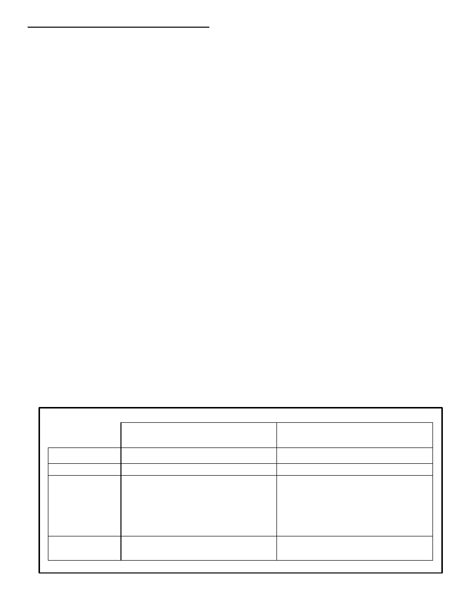
Wire Size: Minimum wire gauge
(AWG) - (based on ASC at maximum current)
Model (V/C)
10‘/3m 20’/6m 30’/9m 40’/12m 10‘/3m 20’/6m 30’/9m 40’/12m
ASC-6/4
14
10
10
8*
14
14
12
10
ASC-12/1
14
14
14
14
14
14
14
14
ASC-12/4
14
14
12
10
14
14
14
14
ASC-12/8
14
10
10
8*
14
14
12
10
ASC-12/12
12
10
8*
6*
14
12
10
10
ASC-12/16
10
8*
6*
4*
14
10
10
8*
ASC-24/8
14
14
12
10
14
14
14
14
ASC-24/16
14
10
10
8*
14
14
12
10
* Wire gauge larger than unit can accept directly. See WIRE SIZE / Large Wires above.
Battery Connection
Distance round trip (feet / meter)
Solar Array Connection
Distance round trip (feet / meter)