SmarTek Systems SAS-1 Setup Using SAS Monitor User Manual
Page 9
SmarTek Systems (www.smarteksys.com)
9
Lane Finder Function display area below the TAI display. The peaks of the LFF show where
each lane should be set, while the valleys indicate quiet space between lanes.
Set the Monitor Mode to 1 (Traffic Acoustic Image Display Mode).
If the Start/Stop button shows Stop then click the Stop button to stop the current display
activity. Click the Zones To Edge button to move all detection zones to the edge of the display.
Click the Save Par button and after it changes to Send Par click the Send Par button. Now
click the Start button. Click in the upper or lower part of the Lane Finder Period (LFP) display
field to set the Lane Finder Period to 3 (3 minutes). Select the Settings/Lane Finder menu item
to show the Lane Finder Function display (Figure 2).
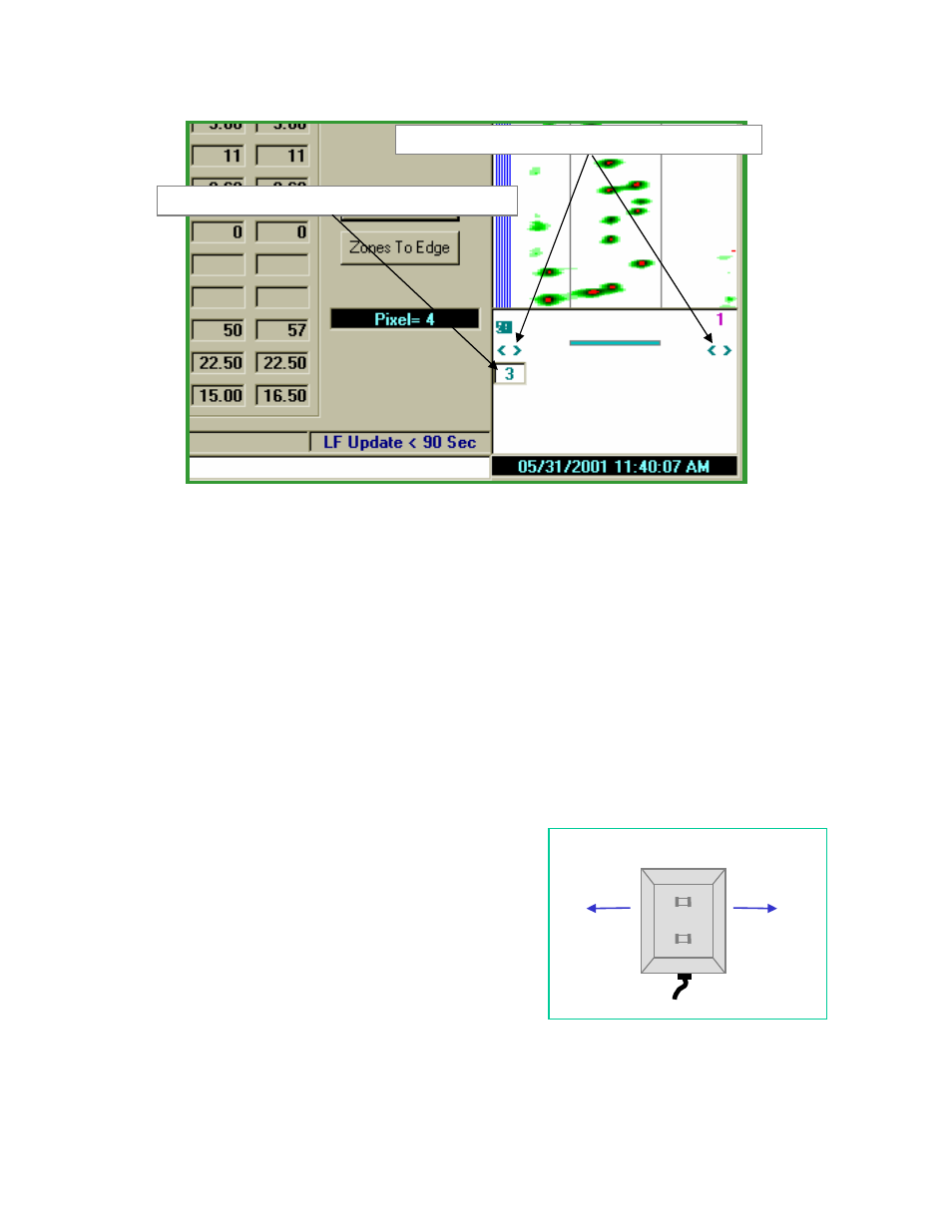
The TAI and Lane Finder displays should look like those shown in Figure 2. Click the
< >
symbols on the left or right side of the Lane Finder
display to set the Lane Finder Function Field. This
field is indicated by the horizontal bar between the
< >
symbols and the gray lines in the TAI display. The
Lane Finder Function will only be computed within the
area indicated by the horizontal bar (and the gray lines
displayed in the TAI). This allows the user to select the
specific set of look directions to be considered for
automatic lane finding. The Number Control shown
on the left side of the Lane Finder Function display
indicates the maximum number of lanes to find (1 to 5).
Clicking this control will increment or decrement the
maximum number of lanes to find.
Figure 2 Begin Lane Finder Functions
Click to Increase/Decrease Number of Lanes/Zones to Set
Click to Increase/Decrease Field for Lane Finder Function
Pixel = 1
Pixel = 181
Figure 3 TAI Orientation