Em-40-sm service manual – Slant/Fin EM-10 Service Manual User Manual
Page 14
14
EM-40-SM Service Manual
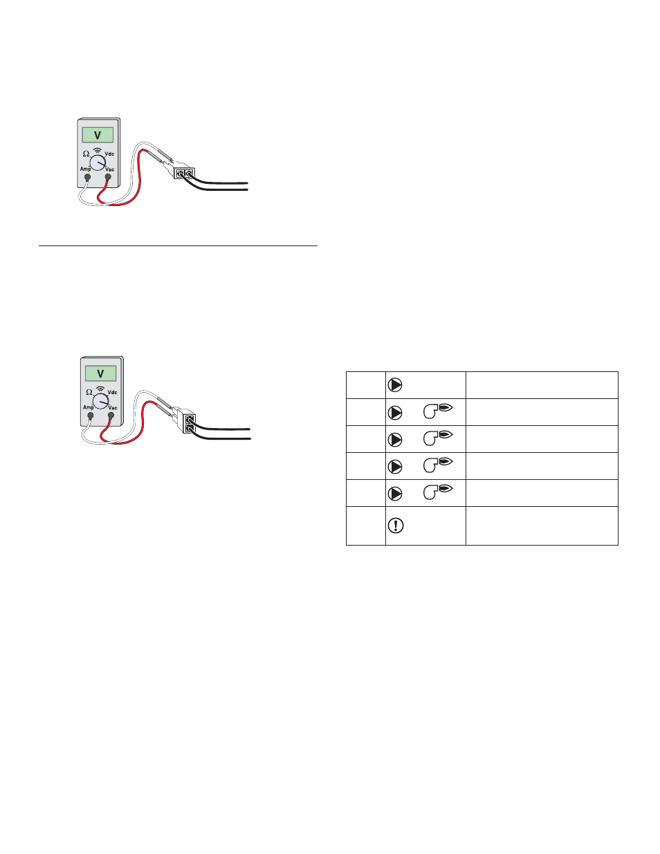
TEST THE POWER SUPPLY
Make sure exposed wires are not in contact with other wires
or grounded surfaces. Turn on the power and measure the
voltage between the C and R pins using an AC voltmeter, the
reading should be between 22 and 26 V (ac).
TEST THE POWERED INPUTS
Heat Demand
If a heat demand is used, measure the voltage between
the CD (common demand) and the Ht D (heat demand)
pins. When the heat demand device calls for
heat, between 20 and 130 V (ac) should be measured at
the pins. When the heat demand device is off, less than 5
V (ac) should be measured.
Setpoint Demand
If a setpoint demand is used, measure the voltage between
the CD (common demand) and the Set D (setpoint demand)
pins. When the setpoint demand device calls for heat,
between 20 and 130 V (ac) should be
measured at the pins. When the setpoint demand device is
off, less than 5 V (ac) should be measured.
Test the External Input
If an external input signal is used, measure the voltage
between the Com/- and +V(in) pins. When the
external control calls for heat, between 0 and 10 V (dc)
should be measured.
CONNECTING THE CONTROL
Make sure all power to the devices and wiring harness
is off.
Reconnect the wiring harness to the connector on the
control by aligning the tab on the wiring harness to the tab
on the connector on the control and then pushing the wiring
harness into the connector on the control. The tab on the
wiring harness should snap over the tab on the connector
of the control.
Apply power to the control. The operation of the control
on power up is described in the Sequence of Operation
section of the brochure.
TESTING THE CONTROL OUTPUTS
The control has a built-in test routine that is used to
override the main control functions. The test sequence is
enabled when the
p
button is pressed and held for 3 sec-
onds while in the View menu. The test sequence can be can-
celled by pressing either the Item,
p
or
q
button. Once the
test sequence is enabled, the outputs are tested in the follow-
ing sequence.
Press and hold the
p
button for 3 seconds while in the
View menu.
22 to 26 V (ac)
20 to 130 V (ac)
Step 1
Boil
The boiler pump is turned on.
Step 2
Boil
1
Stage 1 heating element(s) on.
Step 3
Boil
12
Stage 2 heating element(s) on.
Step 4
Boil
123
Stage 3 heating element(s) on.
Step 5
Boil
1234
Stage 4 heating element(s) on.
Step 6
The boiler pump and stages 1
to 4 are shut off. The alert is
closed for 10 seconds.
The control exits the test sequence and resumes normal
operation.