9 - checking and adjusting co2 levels, 12 - start-up, Warning – Slant/Fin VSL-160C Part B User Manual
Page 31
67
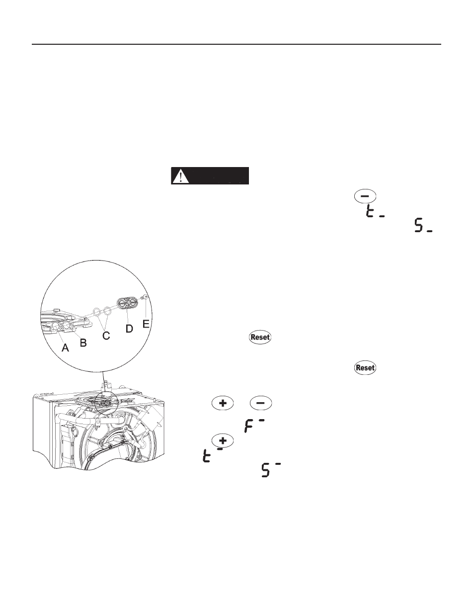
A = air probe
B = fl ue exhaust probe
C = O-ring gaskets
D = cap
E = fi xing screw
Figure 12-6
Combustion
analysis probes
12.9 - Checking and
adjusting CO2 levels
Table 11-3 lists the correct CO2 ranges
for a boiler running at normal operating
conditions at an altitude below 2000
ft (600m). CO2 values outside of the
ranges given in Table 11-3 may lead to
malfunctioning of the boiler and cause
it to prematurely fail. To check the CO2
value, carry out a combustion analysis
as follows while referencing Figure 12-6:
WARNING!!!
During this
procedure compare also CO
(carbon monoxide) reading, with
the value given in Table 11-3. If
this is higher, STOP the boiler
and call the Factory service
department (see phone number
on the last cover page). Failure
to comply with this requirement
could result in severe personal
injury, death or substantial
property damage.
NOTE: During the 10 minutes
override mode, if the demand on
the boiler is low causing the fl ue
gas temperature to increase rapidly,
boiler will go into lock out code L06.
To reactivate it, press
button.
1. carefully remove items “E”, “D” and
“C” from the combustion air/ vent
fi tting:
2. generate a call for heat; and wait up
the boiler is light-on;
4. press the
and
keys for
more than 10 seconds, the display
will show a blinking
;
5. press the
key until the display
shows
if a call for heat has
been generated or until
is
displayed if a domestic hot water
demand has been generated. The
boiler will now run for 10 minutes at
high fi re input;
6. wait 2 to 3 minutes for the CO2 to
stabilize;
7. insert the probe of a calibrated
combustion analyzer into port “B” and
take a fl ue gas sample;
8. compare the CO2 reading with the
high fi re range given in Table 11-3,
making sure to use the range for the
gas type in use. If the CO2 reading
is outside the specifi ed range, it
must be adjusted operating on the
“E” screw of Figure 12-3. Use a
2.5mm Allen Wrench to turn the
screw (clockwise to reduce the CO2
level, counter-clockwise to increase
the CO2 level) in small increments
and wait for the CO2 to stabilize to
prevent overshooting the desired
value;
9. When CO2 level match the value of
Table 11-3, seal screw “E” with red
paint or nail polish to discourage
tampering.
10. press the
key until the
display shows
if a call for heat
has been generated or until
is displayed if a domestic hot water
demand has been generated. The
boiler will now run for 10 minutes at
low fi re input;
11. wait 2 to 3 minutes for the CO2 to
stabilize;
12. compare the CO2 reading with the
low fi re range given in Table 11-3,
making sure to use the range for the
gas type in use. The CO2 reading
must be inside the specifi ed range;
If not, STOP the boiler and call the
Factory service department (see
phone number on the last cover
page).
13. press the
button to return the
boiler to its normal operating mode.
14. close fl ue and air probe “A” and “B”
of Figure 12-6.
15. turn knob “7” and “11” of Figure
13-1 to the OFF position.
12 - START-UP