10 - installation - vent and combustion air, 3 - prepare wall penetrations, 4 - termination and fi ttings – Slant/Fin VSL-160C Part B User Manual
Page 13: 5 - multiple vent/air terminations, Warning
49
10.11.3 - Prepare wall
penetrations
1. Air pipe penetration:
a. Cut a hole for the air pipe. Size the air pipe
hole as close as desired to the air pipe
outside diameter.
2. Vent pipe penetration:
a. Cut a hole for the vent pipe. For
either combustible or noncombustible
construction, size the vent pipe hole with at
least a 1/2 inch clearance around the vent
pipe outer diameter (4½ inch hole for 3
inch vent pipe)
b. Insert a galvanized metal thimble in the
vent pipe hole as shown in Figure 10-19.
3. Use a sidewall termination plate as a template
for correct location of hole centers.
4. Follow all local codes for isolation of vent pipe
when passing through fl oors or walls.
5. Seal exterior openings thoroughly with
exterior caulk.
10.11.4 - Termination and
fi ttings
1. The air termination coupling must be oriented
at least 12 inches above grade or snow line
as shown in Figures 10-17 and 10-18.
2. Maintain the required dimensions of the
fi nished termination piping as shown in
Figures 10-17 and 10-18.
3. Do not extend exposed vent pipe outside
of the building more than what is shown in
Figures 10-17 and 10-18. Condensate could
freeze and block vent pipe.
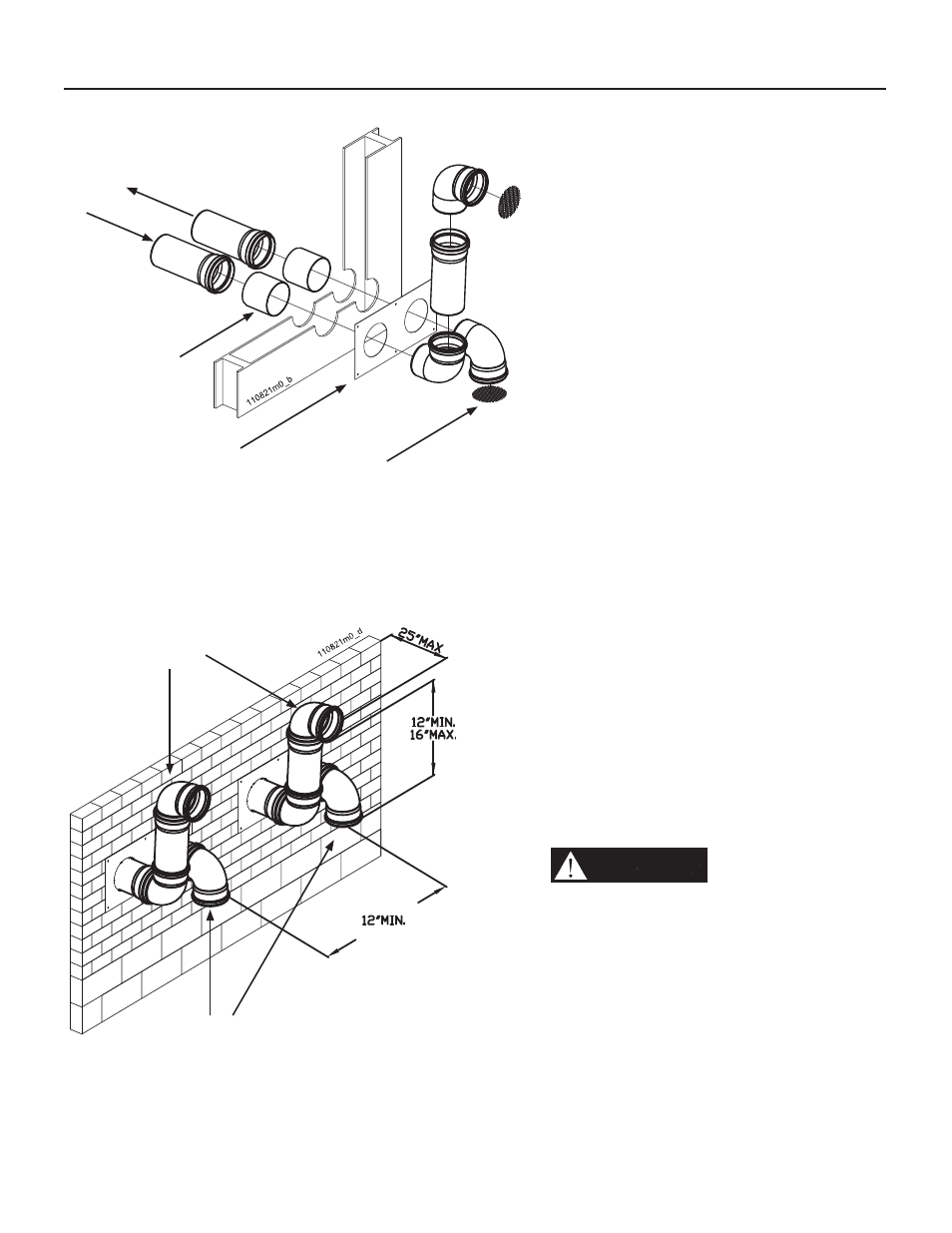
10.11.5 - Multiple vent/air
terminations
1. When terminating multiple boilers terminate
each vent/air connection as shown in Figure
10-20.
WARNING!!!
All vent pipes and air
inlets must terminate at the same height
to avoid possibility of severe personal
injury, death, or substantial property
damage.
2. Place wall penetrations to obtain minimum
clearance of 12 inches between edge of
air inlet and adjacent vent outlet, as shown
in Figure 10-20 for U.S. installations. For
Canadian installations, provide clearances
required by CSA B149.1 Installation Code.
3. The air inlet is part of a direct vent connection.
It is not classifi ed as a forced air intake with
regard to spacing from adjacent boiler vents.
10 - INSTALLATION - Vent and combustion air
Figure 10-19 Two pipes sidewall termination
assembly
Figure 10-20 Two pipes multiple boilers vent
terminations
Air intake
Flue exhaust
Metal thimble
Termination
template
Bird screen
NOTE: keep the air intake at min. 12” from grade or
snow line. Provide vent and air intake with bird screen
Vent terminals
Air intake
between edge
of each air
intake pipe
Same distance
for vent
terminal