10 - installation - vent and combustion air, Warning – Slant/Fin VSL-160C Part B User Manual
Page 12
48
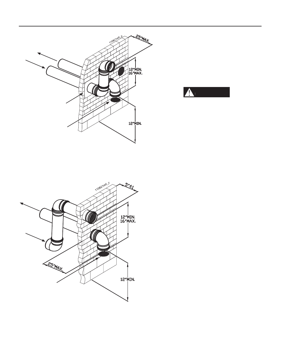
3. The air piping must terminate in
a down-turned elbow as shown
in Figures 10-17 and 10-18. This
arrangement avoids recirculation of
fl ue products into the combustion
air stream.
4. The vent piping must terminate
in an elbow pointed outward or
away from the air inlet, as shown in
Figures 10-17 and 10-18.
WARNING!!!
Do not
exceed the maximum lengths
of the outside vent piping
shown in Figures 10-17 and 10-
18. Excessive length exposed
to the outside could cause
freezing of condensate in the
vent pipe, resulting in potential
boiler shutdown.
5. Maintain clearances as shown in
Figures 10-17 and 10-18. Also
maintain the following:
a. Vent must terminate:
• At least 6 feet from adjacent
walls.
• No closer than 12 inches below
roof overhang.
• At least 7 feet above any public
walkway.
• At least 3 feet above any forced
air intake within 10 feet.
• No closer than 12 inches below
or horizontally from any door
or window or any other gravity
air inlet.
b. Air inlet must terminate at least
12 inches above grade or snow
line; at least 12 inches below the
vent termination;
c. Do not terminate closer than 6
feet horizontally from any electric
meter, gas meter, regulator, relief
valve, or other equipment. Never
terminate above or below any of
these within 6 feet horizontally.
6. Locate terminations so they are
not likely to be damaged by foreign
objects, such as stones or balls,
or subject to buildup of leaves or
sediment.
Figure 10-18 Two pipes
sidewall termination of
air and vent (if space permits)
10 - INSTALLATION - Vent and combustion air
Figure 10-17 Two pipes sidewall termination
of air and vent
Air intake
Flue exhaust
Grade/Snow level
Bird screen
Air intake
Flue exhaust
Termination
template
Grade/Snow level
Bird screen