7 - gas supply pressure checking, 12 - start-up, Warning – Slant/Fin VSL-160C Part B User Manual
Page 29
65
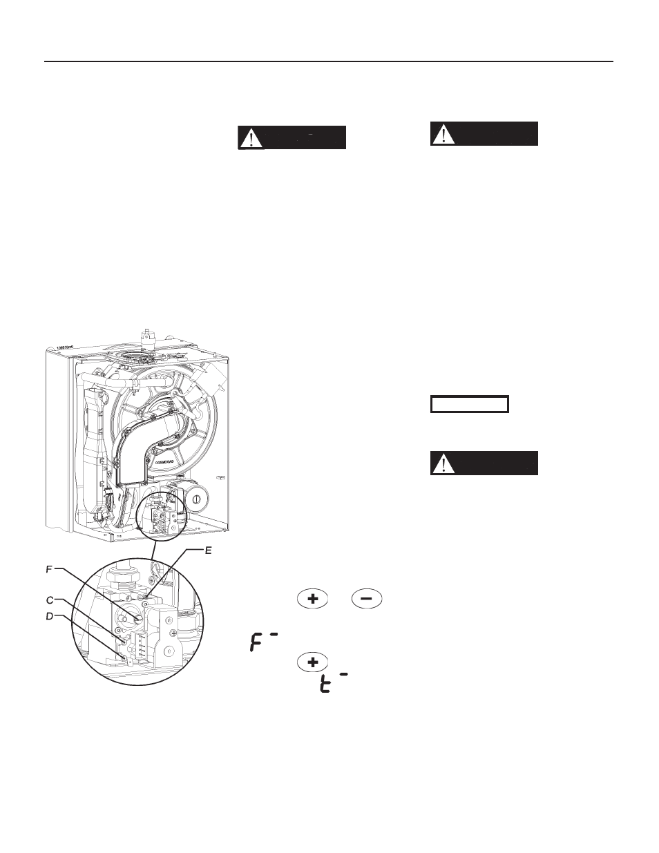
Figure 12-3 Gas valve
C -
Service pressure probe
D - Inlet gas pressure probe
E - CO2 adjusting screw
F - Factory adjusted regulator
(Should never be touched)
12.7 - Gas supply
pressure checking
WARNING!!!
DO NOT
adjust or attempt to measure
gas valve outlet pressure. The
gas valve is factory-set for the
correct outlet pressure. This
setting is suitable for natural
gas and propane, requiring no
fi eld adjustment. Attempting to
alter or measure the gas valve
outlet pressure could result in
damage to the valve, causing
potential severe personal
injury, death, or substantial
property damage.
Check the gas supply pressure by
following the steps below:
1. close the manual gas shut-off
valve, Figure 11-1;
2. follow the steps in Section 14.2 to
remove the front cover;
3. turn the screw in pressure port “D”
shown in Figure 12-3 three turns
counterclockwise;
4. connect a manometer with
graduations of at least 0.1 in.W.C.
(0.25 mbar) to the inlet gas port “D”
shown in Figure 12-3;
5. open the manual gas shut off valve,
Figure 11-1;
6. check that the gas supply pressure
does not exceed 13 in.W.C.;
7. turn the power switch to on and
generate a heat demand by turning
knob “7” shown in Figure 13-1 to its
maximum setting. Also ensure that
the room thermostat is calling for
heat;
8. press the
and
keys
at the same time for more than
10 seconds, the display will show
;
9. press the
key until the
display shows
. Now the
boiler will run for 10 minutes at
maximum input;
10. check the manometer to make
sure the gas supply pressure does
not drop below 3 in.W.C. (7.6
mbar).
If the gas supply pressure does not
fall within 3 and 13 in.W.C. adjust the
upstream gas pressure regulator to
bring the gas supply pressure within
the above values.
WARNING!!!
DO NOT
adjust the screws “E” and/or
“F” (Figure 12-3). These screws
are factory-set for the correct
gas fl ow and outlet pressure.
Attempting to alter the gas
valve setting could result in
damage to the valve, causing
potential severe personal
injury, death, or substantial
property damage.
After verifying the correct gas
pressures:
1. close the manual gas shut-off
valve, Figure 11-1;
2. disconnect the manometer;
3. turn the screw in pressure
connection “D” in Figure 12-3,
clockwise until snug;
4 check for any gas leaks.
CAUTION!!!
Never force the
pressure connection screw or
the gas valve will be damaged!
WARNING!!!
Never use an
open fl ame to check for gas
leaks, a fi re or an explosion
could result causing severe
personal injury or death!
12 - START-UP