Slant/Fin Gas Steam User Manual
Page 6
6
GAS PIPING
This section contains sizing and construction recommendations
for fuel supply piping to Caravan gas-fired modular boiler sys-
tems. Gas-fired equipment must conform not only to codes of the
local regulatory agencies, but also to additional specifications
that may be imposed by the utility or gas supplier. Therefore, the
following information should be considered only as a guideline.
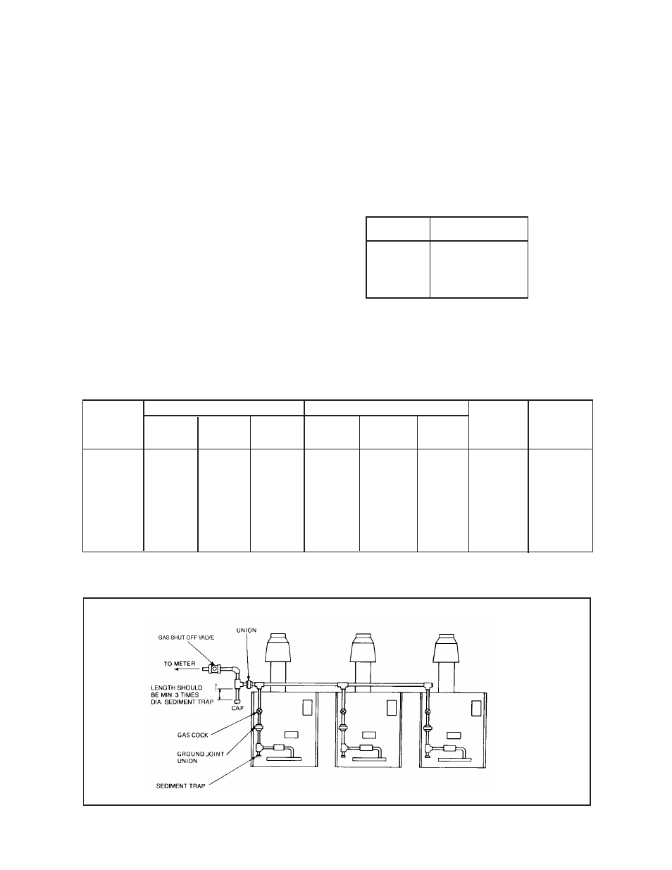
Figure 5 illustrates a typical gas supply line installation. It con-
sists of a main between the utility’s meter box and the boiler sys-
tem, a main shut-off valve, sediment trap, gas header pipe and
drip legs on individual boilers.
Individual gas lines to individual boiler modules should be
3
⁄
4
-inch
diameter. Size of gas main header pipes depends on volume of
gas required and acceptable pressure drop between meter and
modules’ gas regulator valves. Minimum pressure required at
each valve is 5-inches of water column for natural gas and 11-
inches for propane gas, measured while all boilers and other gas-
fired equipment on the same meter are firing. Small variations in
gas flow can be compensated for by adjusting gas regulator
valves. However, final pressure of gas header must vary no more
than + 0.3-inches of water column.
GAS MAIN SIZING
To determine the correct pipe diameter for the gas main serving a
specific Caravan system, proceed as follows:
a. Follow the building plans, find total length of straight pipe
between supply from gas meter and boiler gas header.
b. Using data in Table 5, calculate equivalent linear length of
screw pipe fittings used in fabrications of main. Add this to
figure from step (a) to obtain equivalent total length.
c. Find Caravan gas consumption in cubic feet per hour from
Table 4.
d. Multiply the system total hourly gas consumption by flow
correction value from Table 6, page 7.
e. Locate system’s total equivalent pipe length in right column of
Table 7.
f. Move vertically to the system’s corrected flow rate calculated in
step (c). If this value falls between two of those listed, select
larger value.
g. From this point, move horizontally to the left column and read
suggested pipe diameter for gas main.
Table 4: Gas Consumption Rate
GXHT600Z
600
GXHT900Z
900
GXHT1200Z
1200
GXHT1500Z
1500
Model No.
Gas
Consumption in CFH
1
⁄
2
0.84
0.52
0.41
0.031
2.50
1.12
1.25
1.66
3
⁄
4
1.17
0.73
0.57
0.044
3.50
1.84
1.75
2.33
1
1.57
0.98
0.77
0.057
4.68
2.11
2.34
3.11
1
1
⁄
4
2.19
1.37
1.07
0.082
6.54
2.94
3.27
4.35
1
1
⁄
2
2.63
1.64
1.29
0.098
7.84
3.52
3.92
5.21
2
3.55
2.23
1.74
1.320
10.60
4.77
5.30
7.05
3
5.72
3.59
2.81
2.130
17.08
7.69
8.84
11.40
Pipe
Size
Inches
Standard
Table 5: Equivalent linear length in feet of standard iron pipe fittings for natural gas
Medium
Sweep
Long
Sweep
Gate
Globe
Angle
Return
Bend
Side
Outlet
Tee
Elbow
Valve
Figure 5: Typical gas supply line installation