Slant/Fin Gas Steam User Manual
Page 14
14
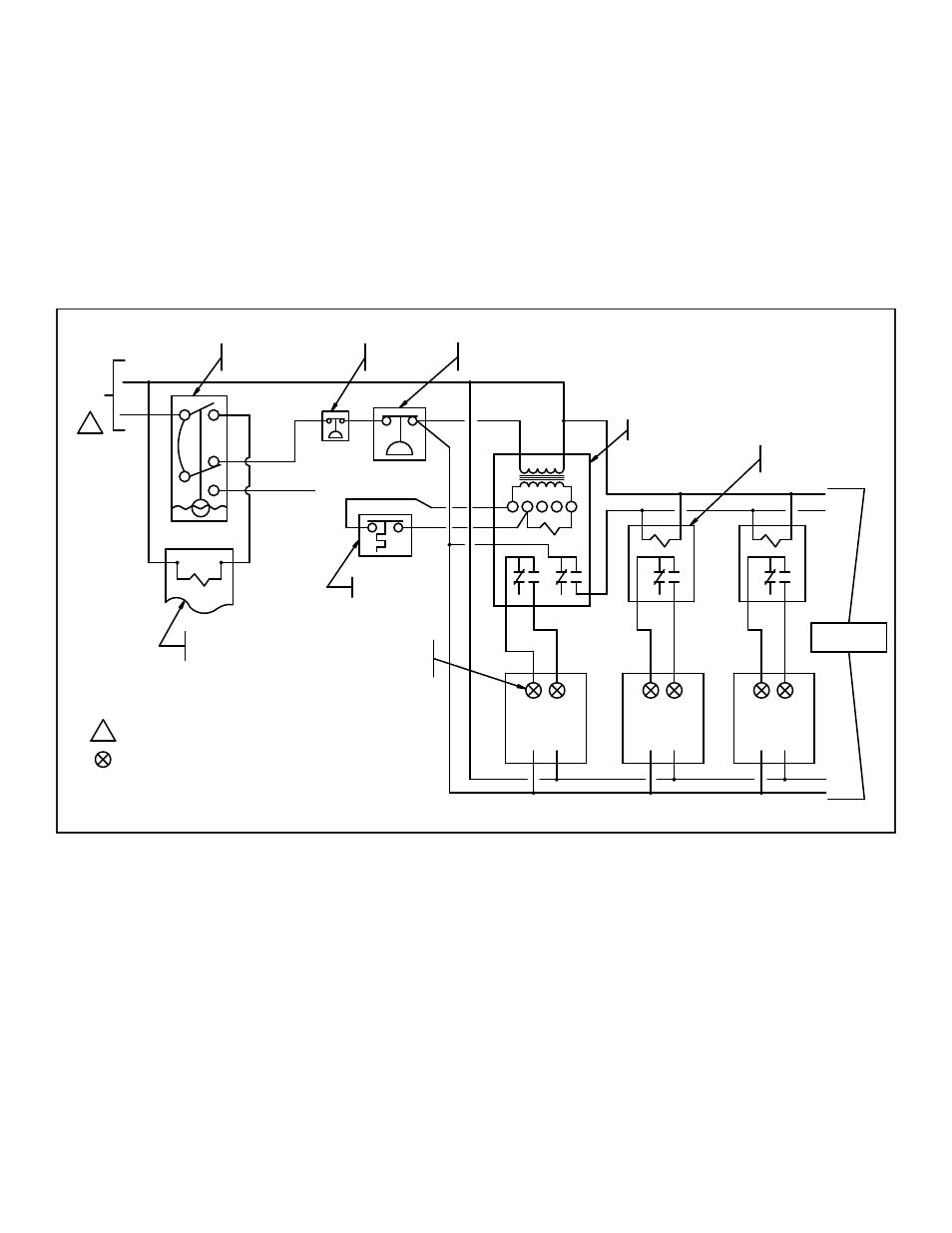
Sequence of operation
When the building thermostat calls for heat, contacts (RC) of the
R8285B control closes. This energizes the coils of R1 and R2
relays. With these contacts closed all the modules are energized
to fire. This will bring the system pressure up quickly. The P404A
pressure controls on each module (not shown in diagram, see fig.
16) are set to the pressure required to heat the building. This will
stage the number of modules firing to meet the demands of the
building load. The required modules will continue to fire until the
thermostat is satisfied.
There are several manufacturers that provide more sophisticated
controls for modular steam systems.
MODULAR STEAM WITH SPACE TEMPERATURE CONTROL WIRING DIAGRAM
R
G
Y
W
C
MODULE 1
MODULE 2
BUILDING
THERMOSTAT
L4079B
MANUAL RESET
HI LIMIT PRESSURETROL
R8285B
TRANSFORMER/RELAY
PROVIDE OVERLOAD AND DISCONNECT
1
MEANS AS REQUIRED.
1
H
N
N
H
N
H
#42A LOW WATER
CUT-OFF & PUMP
1
2
5
6
4
CONTROL
120
VAC
CONTACTOR OR
BOILER FEED PUMP
STARTER FOR
FIELD SUPPLIED
TO SYSTEM
ALARM
DWG FILE #WIRING\0000051W
21-1/4"
22-3/4"
RESET
MANUAL
#67M LWCO
(IF REQUIRED)
MODULE 3
H
N
5 MODULES
MAXIMUM
ETC.
ETC.
RELAY
COIL (TYP)
120 VOLT
- FOR CONNECTIONS SEE WIRING AT
RC
R1
R2
MODULE ON PAGE NO. 16
AT MODULE ON
SEE WIRING
FOR CONNECTIONS
ON PAGE NO. 16
Figure 14: Space temperature control wiring diagram