SilentKnight SK-Beam / SK-Beam-T Addressable Beam Smoke Detector w/Test User Manual
Page 5
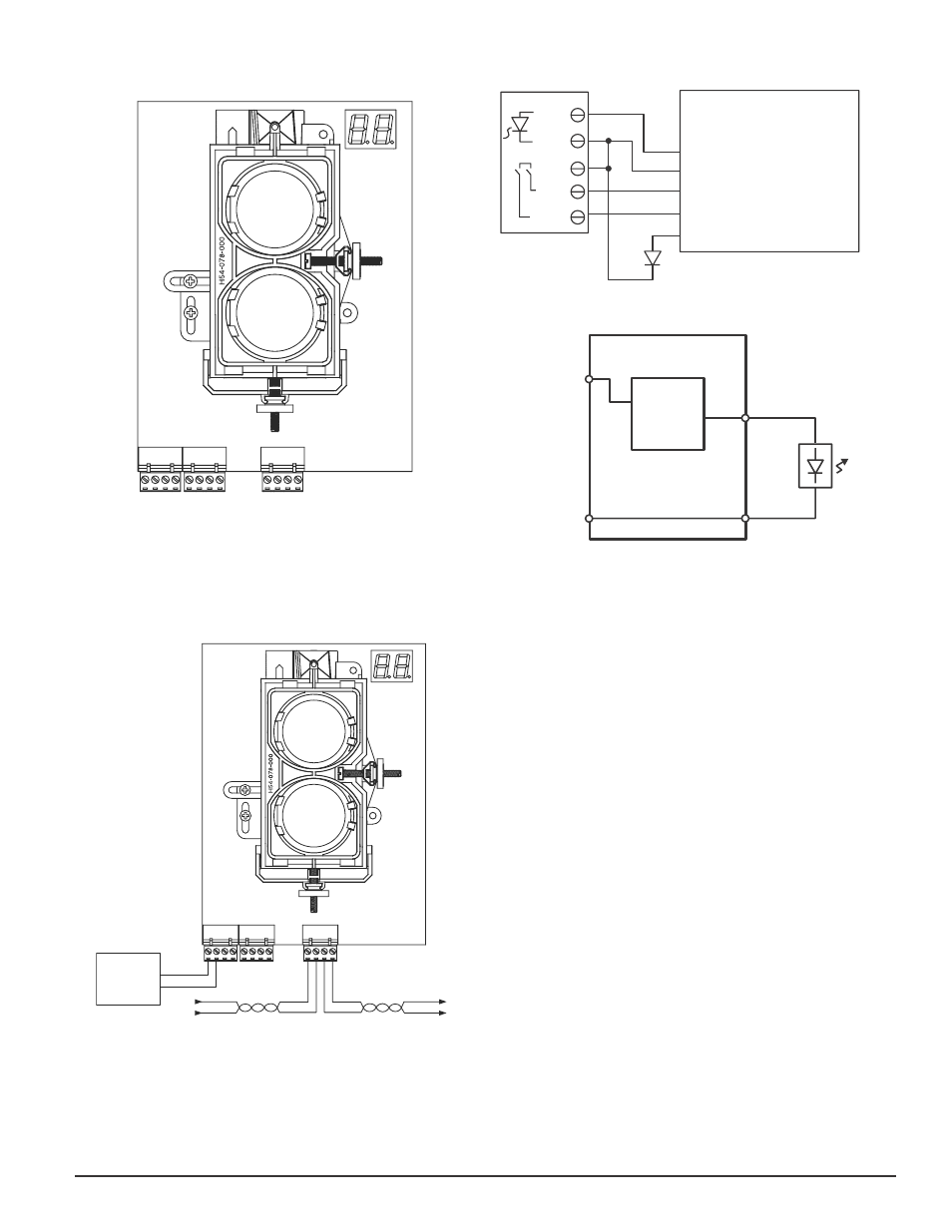
fIGURE 6. wIRING CONNECTIONS AT DETECTOR
SLC (–
)
SLC (+)
SLC (–
)
SLC (+)
RESET
I NPUT
TEST
INPU
T
AUX (–)
REMOTE
ALARM OUT
NOT
USED
REMOTE
TROUBLE OUT
TEST
OPTION (–)
TEST
OPTION (+)
T3
T2
T1
C0260-01
fIGURE 7. wIRING DIAGRAM
+ с
+
с
+
+
TO NEXT
DEVICE
FROM PANEL OR
PREVIOUS DEVICE
LISTED
REMOTE
POWER
SOURCE
* Only used for
SK-BEAM-T. See
electrical ratings.
COMMUNICATION LINE
32 VDC MAX.
TWISTED PAIR IS
RECOMMENDED.
с
с
с
+
T3
T2
T1
fIGURE 8. wIRING DIAGRAM (RTS451/RTS151)
RTS451/RTS451KEY
or RTS151/RTS151KEY
DETECTOR
PIN 1
REMOTE ALARM OUT
T2-1
T2-2
T2-4
T2-3
AUX (–)
SLC IN +
T1-1
T1-2
T1-3
T1-4
SLC IN –
SLC OUT +
SLC OUT –
RESET INPUT
TEST INPUT
T3-3 REMOTE TROUBLE OUTPUT
OPTIONAL YELLOW LED
PIN 2
PIN 4
PIN 3
PIN 5
fIGURE 9. wIRING DIAGRAM (RTS451/RTS151)
BDT-SS
Alarm
Signal
Circuit
(Note 1)
T2-1
T2-2
Note 1: See electrical ratings section of this
manual for circuit output ratings.
SLC (+)
SLC (–)
Red
C0369-00
INSTALLATION / ALIGNMENT
Reference Figures 10 through 14 for installation, alignment, and maintenance.
The alignment of the SK-Beam/SK-Beam-T is divided into four steps: coarse
alignment, fine adjustment, final gain adjustment, and final verification. It is
necessary for all four steps to be executed properly to ensure proper alignment
of the product. If the detector and reflector are mounted per Mounting Loca-
tions and Mounting Instructions sections of this manual and the alignment
procedures are executed properly, false alarms and nuisance trouble signals
will be minimized.
Pre-Alignment CheCklist
Insure that both the detector and reflector are mounted securely to stable
•
surfaces.
Insure that all wiring is correct.
•
Insure that terminal blocks are fully seated into their receptacles on the
•
detector.
Complete any wiring dressing to minimize movement to the detector once
•
the alignment procedure is completed.
Insure that the appropriate number of reflectors are used for the installed
•
distance. Distances between 230 and 328 Feet (70 – 100m) require ad-
ditional reflectors (4 total). The BEAMLRK accessory should be used in
these cases.
Insure that the line of sight between the detector and reflector is clear
•
and that reflective objects are not too near. See Mounting Instructions
for more details.
Insure that both the detector and reflector are mounted within their
•
operational parameters for off axis angles. See Mounting Instructions
for more details.
Disable the zone or system to prevent unwanted alarms before applying
•
power.
Insure power to the detector is “ON”.
•
Insure that the appropriate address is set on the code wheels.
•
You are now ready to begin the alignment procedure.
SK-400-007
5
I56-3433-001R
C0335-03
C0328-06