SilentKnight SK-Beam / SK-Beam-T Addressable Beam Smoke Detector w/Test User Manual
Page 3
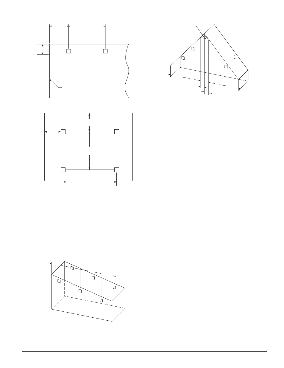
fIGURE 1. SpACING fOR SMOOTh CEILING (SIDE vIEw):
1
/
2
S
S
12 - 18 IN.
(0.3 - 0.46M)
WALL
C0254-00
fIGURE 2. SpACING fOR SMOOTh CEILING (TOp vIEw):
16 FT. (5M) MINIMUM
328 FT. (100M) MAXIMUM
Tx/Rx
REFLECTOR
S
Tx/Rx
REFLECTOR
1
/
2
S MAXIMUM
1
/
4
S
MAX.
C0255-00
In the case of peaked or sloped ceilings, codes may specify spacing of detec-
tors by using horizontal spacing from the peak of the roof or ceiling. Figures
3 and 4 show the spacing for both the shed type and peaked type sloped
ceilings.
On smooth ceilings, beam smoke detectors should generally be mounted be-
tween 12 and 18 inches (0.3 to 0.46m) from the ceiling. In many cases, how-
ever, the location and sensitivity of the detectors shall be the result of an
engineering evaluation that includes the following: structural features, size
and shape of the room and bays, occupancy and uses of the area, ceiling
height, ceiling shape, surface and obstructions, ventilation, ambient environ-
ment, burning characteristics of the combustible materials present, and the
configuration of the contents in the area to be protected.
fIGURE 3. SLOpED CEILING (ShED TypE):
S
3 FT.
(0.9M)MAX.
S
1
/
2
S MAX.
Tx/Rx
REFLECTOR
C0256-00
fIGURE 4. SLOpED CEILING (pEAKED TypE):
1
/
2
S
S
S
1
/
2
S
3 FT. (0.9M)
MAX.
3 FT. (0.9
M)
MAX.
MOUNT DETECTOR
ANYWHERE IN
THIS AREA
Tx/Rx
REFLECTOR
C0257-00
MOUNTING LOCATIONS
Beam detectors require a stable mounting surface for proper operation. A sur-
face that moves, shifts, vibrates, or warps over time will cause false alarm or
trouble conditions. Initial selection of a proper mounting surface will elimi-
nate false alarms and nuisance trouble signals.
Mount the detector on a stable mounting surface, such as brick, concrete,
a sturdy load-bearing wall, support column, structural beam, or other sur-
face that is not expected to experience vibration or movement over time. DO
NOT MOuNT the beam detector on corrugated metal walls, sheet metal walls,
external building sheathing, external siding, suspended ceilings, steel web
trusses, rafters, nonstructural beam, joists, or other such surfaces.
In cases where only one stable mounting surface as defined above can be used,
the transmitter/receiver unit should be mounted to the stable surface and the
reflector should be mounted to the less stable surface. The reflector has a
much greater tolerance for the unstable mounting locations defined above.
MOUNTING INSTRUCTIONS
The transmitter/receiver unit may be mounted over a recessed junction box.
The cavity behind the detector is then used for routing of the wiring from the
junction box to the terminal blocks on the detector. The transmitter/receiver
unit should be mounted to the wall such that unit covers the recessed junc-
tion box in the wall completely. If the junction box is not recessed then you
may use the surface mount kit (BEAMSMK). See the BEAMSMK installation
instructions for surface mounting instructions. The transmitter/receiver unit
can be mounted to the wall using the supplied drilling template (see Appendix
II). The detector base has 4 primary mounting keyholes, one in each corner of
the base. All four hole locations should be used to provide a secure mounting.
The outer housing of the beam detector is held to the base using four screws.
In order to mount the detector you must remove the outer housing first.
The reflector can be mounted to the wall using the supplied drilling template
(see Appendix III). The reflector has 4 mounting holes, one in each corner.
All four hole locations should be used to provide a secure mounting. The
reflector must be mounted such that it is within 10° in both the X and Y
planes of the transmitter/receiver unit. See Figure 5a. The reflector must also
be mounted such that plane of the reflector is perpendicular to the optical
line of sight to the transmitter/receiver unit. The maximum tolerance for non-
perpendicular mounting locations is 10°. See Figure 5b. If the reflector cannot
be mounted within 10° of the transmitter/receiver unit then the multi-mount
kit (BEAMMMK) may be used to provide greater angular adjustment of the
transmitter/receiver unit. If the perpendicular plane of the reflector cannot be
mounted within 10° of the optical line of sight then the multi-mount kit can be
used for the reflector. See BEAMMMK instructions.
To aid in locating the reflector in the alignment mirror at long distances a
bright orange sticky backed piece of paper is provided. Remove the protective
backing from the orange sticker. Temporarily affix the orange paper next to
the reflector using the sticky backing of the paper. The location of the sticky
paper is not critical. It may be placed anywhere near the reflector as long as it
not covering the reflective surface of the reflector. This sticky paper should be
removed once the installation is completed.
SK-400-007
3
I56-3433-001R