Other controls – Reznor ZQYRA Parts Manuals User Manual
Page 4
Form P-ZQYRA, PN262961R2, Page 4
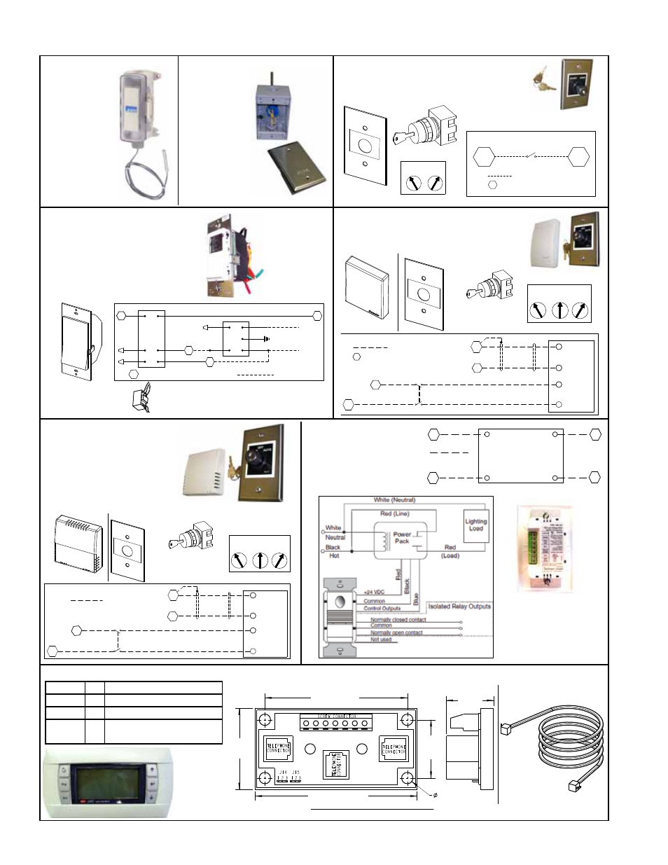
Other Controls
START
STOP
START
STOP
2 Key Positions
KEY LOCK
POWER SWITCH
CN5
2-Position (start/stop)
Key Switch, P/N 260227
Cover, P/N 260229
Label, P/N 260228
Reference
Components and wiring information for
Option CN5.
8
3
= field wiring
= field connection terminal block in the
electrical compartment of the unit
Multi-Voltage Relay Module, P/N 260189, used with
Option CN7A is mounted in the electrical compartment
at the factory; see Code 12 on page 3.
Time ClockWall Switch,
Leviton Model VPT24-1P,
P/N 260188
BK
BL
W
O
R
BK
W
Y/R
R
G/Y
(HOT) BK
(NEUT) W
}
115/1/60
LINE
PAM-1
TIMER
SWITCH
Y
22
23
BL
8
Multi-voltage
relay
(see below)
3
= field wiring
= field connection terminal block
CO2 Sensor,
P/N 234820
Keyed, 3-Position Wall
Switch, P/N 260230
Cover, P/N 260229
Label, P/N 260231
3 Key Positions
HAND
OFF
AUTO
HAND
AUTO
OFF
Reference
11
SW2 AUTO & HAND
AUTO
SW1
8
SHIELD
2
GROUND
4
SIGNAL
CO2 SENSOR
SHIELD
(OPT. CN7B)
2
POWER
1
GROUND
SWITCH
KEYED
9
3
= field wiring
= field connection terminal block
in the electrical compartment of
the ventilation unit
CODE 30 - Wall Mounted,
Manual Start/Stop Switch, P/N
260431 (same as Option CN5)
CODE 31- Time Clock
Wall Switch, P/N 260432
(same as Option CN7A)
CODE 32 - CO2 Sensor, P/N
260433 (same as Option CN7B)
CODE 33 - Indoor Air
Quality (VOC and CO)
Sensor, P/N 260434
(same as Option CN7C)
COM
RELAY OUTPUT
COMM
INPUT POWER
24V IN
N.O.
OCCUPANCY SENSOR
PW-100-24
OPT. CN7D
8
11
10
3
= field wiring
CODE 34 -
Space-mounted
Occupancy Switch,
P/N 260435 (same
as Option CN7D)
P/N Qty Description
260178 1 Unit Display
260175 2 6-pin Connection Cable
260735 2 Cable Splitter and Signal
Booster Module
1.56”
(40mm)
(2) Cable Splitter and Signal Booster Modules, P/N 260735
2.75 (70mm)
3.13” (80mm)
Front and Side Views with Dimensions
.219”
(6mm)
1.125”
(29mm)
.91”
(23mm)
(2) 6-pin Connection
Cables, P/N 260175
6
0
A
B
S
Unit Display,
P/N 260178
CODE 35 - Remote Unit Display Kit, P/N 260436 (same as Option RB5)
CODE 29 -
Discharge
Air
Temperature
Sensor, P/N
222753 (2)
CODE 28 -
Humidity
and
Temperature
Sensor,
P/N 260170
VOC and CO
Sensor, P/N 260192
Keyed, 3-Position Wall
Switch, P/N 260230
Cover, P/N 260229
Label, P/N 260231
3 Key Positions
HAND
OFF
AUTO
HAND
AUTO
OFF
Reference
11
SW2 AUTO & HAND
SW1 AUTO
8
SHIELD
1 GROUND
3 SIGNAL
IAQ SENSOR
SHIELD
(OPT. CN7C)
1
POWER
2
GROUND
SWITCH
KEYED
3
9
3
= field wiring