Figure 5 - wiring diagram for installing relay – Reznor VR Option - Installation - Outside Air Kit User Manual
Page 4
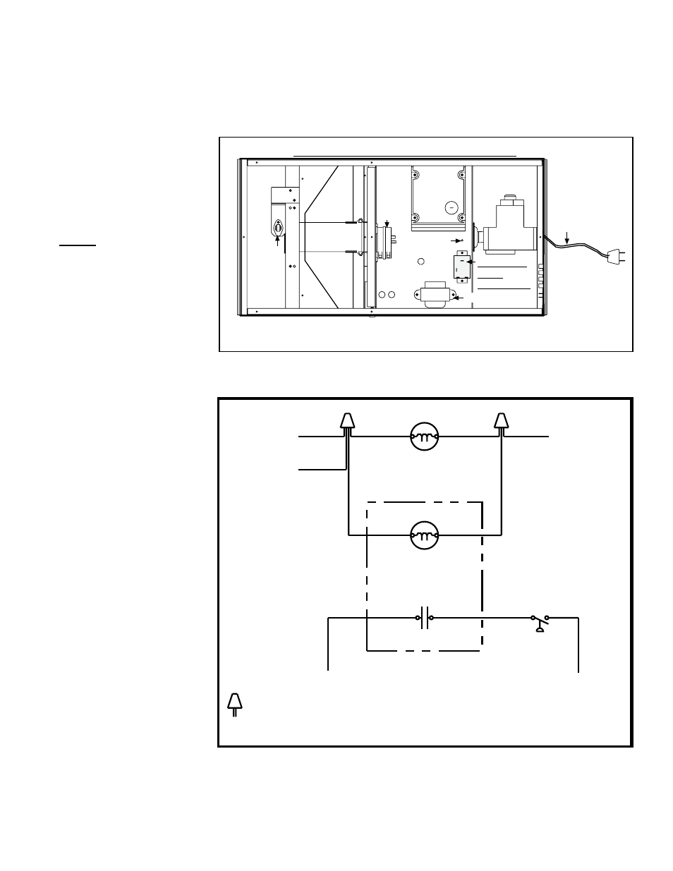
Form I-VR-OA, P/N 205406 (Rev 3), page 3
FIGURE 4 - Attach
relay in location
shown and connect
wires according to
the wiring diagram in
FIGURE 5.
NOTE: When using
outside air, the
pressure switch will
sense high outdoor
wind, and the pressure
switch contacts will
close.
The relay
permits a “call for
heat” during high
wind conditions and
prevents a nuisance
problem of the DSI
control going into
lockout.
���
�����
��������������������������������������
����������
������
����������
����������
��������
����������
�������� ������
�
����
���������
�����������
��������������
����������������������
���������������
�������������������������������������
���
��������
�����
������
�����
������
�
�
�
�
��
�
�����������
�����
�
�
�
�
�����������
�����������
�����������
�����������
������
�����
��
�
����
��������
���������
�����������
��
��
�
�
��
�����������
�����������
��������������������������������������������������������������������
��������������������������������������������������������������������������
����������
���������������
�
�
�
��������������
������
FIGURE 5 - Wiring
diagram for installing
relay.
supplied piping that extends to the outside air inlet terminal. Do not extend
the flexible pipe more than three feet (.9M) as it must be able to expand
and contract with the heater.
5) Install the Relay - Open the control access door on the burner/control
box. Locate the two holes between the transformer and the ignition control-
ler (See
FIGURE 4). Install the relay using the screws provided.
Wire the relay according to the wiring diagram in
FIGURE 5 or the label in
the kit.
6) Close the control access door and adhere the wiring diagram label to the
rear of the burner box.
During unit startup, check for proper operation.