Installation instructions – Reznor VR Option - Installation - Outside Air Kit User Manual
Page 3
Form I-VR-OA, P/N 205406 (Rev 3), page 2
�����������
�����������
������
��������������
��������������
���
�������
�������
����
�������
�������
�������
���
�������
�������
��������������������������������������
����������������������������������
����������������������������������������
����������
�������
���������
����������
�����������������������
����������������������
�����������������������
�����������
������������������������������
�����������������������������
���������������������������
������������������������
����������������������������
�����������������������
�������������������������
�����������������������
�������������������
��������������������
������������������������������
�������������������
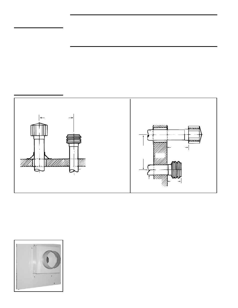
FIGURE 2B - Horizontal Vent and
Inlet Air
FIGURE 2A - Vertical Vent and Inlet Air
2) Install the Inlet Air Pipe (field supplied) - Install the inlet air pipe from the
outside terminal to within a maximum of three feet (.9M) of the burner/con-
trol box. If the inlet air pipe passes through moisture-laden air, insulation or
double-wall tubing may be needed to prevent condensation on the outside
of the pipe. Provide adequate support.
3) Attach the Combustion Air Inlet Cover (FIGURE 3) - Align the hex huts
on the combustion air inlet side of the burner/control box with the holes in
the sheetmetal drill template. Using the outer four holes in the template,
mark and drill four 7/64” diameter holes for attaching the air inlet cover.
Attach the air inlet cover using the screws provided.
4) Install Expandable Pipe - Use one clamp to attach the expandable pipe to
the air inlet cover. Use the other to attach the expandable pipe to the field-
FIGURE 3 - Position
template and mark
holes on side of
burner box. Drill
holes and attach the
combustion air inlet
cover.
) Install Air Inlet Terminal - Install outside terminal portion of the air inlet.
See requirements for a vertical vent in the illustration in
FIGURE 2A or
horizontal vent in
FIGURE 2B.
Use only the inlet cap included in the option kit. A different combustion air
inlet cap could cause nuisance problems and/or unsafe operating condi-
tions.
Installation
Instructions
WARNING: If
the heater is
installed, turn
off the gas and
disconnect
the electric
before installing
the optional
combustion air
inlet kit.
Read all instructions before proceeding; do steps in the order that
best suits the installation.
WARNING: This outside air kit is to be installed by a qualified
service person in accordance with these instructions and
in compliance with all codes and requirements of authori-
ties having jurisdiction. The qualified agency performing this
work assumes responsibility for this installation.
If the inlet cap is located adjacent to the exhaust terminal, the terminals
must be separated by a minimum distance of three feet (.9M). The only
exception is when the air inlet is located directly below a horizontal vent
cap. The required clearance between an air inlet terminal located directly
below the vent cap is 18” (457mm).
NOTE: The vent and the fresh air
intake may be installed in different pressure zones.