Installation instruction, Warn ing – Reznor P6SP Option - Installation - Power Exhaust - Light Commercial User Manual
Page 2
INSTALLATION
INSTRUCTION
INSTALLATION INSTRUCTIONS FOR
POWER EXHAUST USED WITH Q5SN AND
R4G(M,N)-090/120 (R-22) UNITS AND P6SP, R6SP,
Q6SP-072/120 (R410A) UNITS
Important - DO NOT cut other wires. Inspect for damaged connections or loose wires.
3.
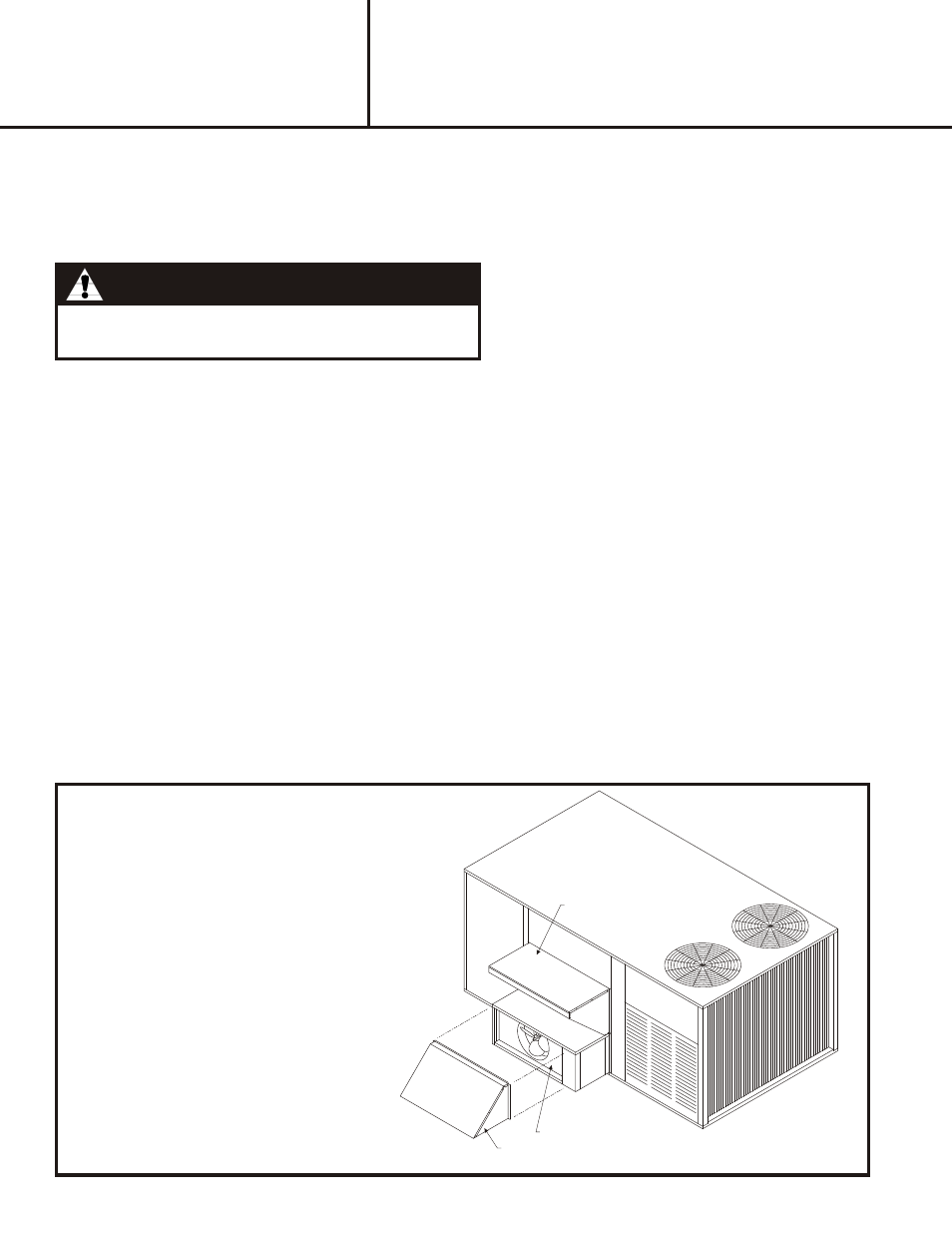
Remove the barometric relief hood of economizer, if previously installed, and retain screws for later use. See Figure 2.
Notice to Installer: This accessory provides a switch for sensing economizer operation and will need to be
mounted and wired to the economizer prior to installation of the power exhaust unit. See installation instructions
provided with the switch for set up and connection to economizer for proper power exhaust operation.
Warn ing:
All electrical wiring must comply with the latest edition
of the National Electrical Code (NEC) - NFPA 70.
For R4G(M,N)- 090/ 120 (R-22) Models - IMPORTANT: See unit rating label before operating this accessory to
ensure correct field supply wire size has been installed to the unit for proper operation of this accessory.
4
Remove plastic hole plug (located on economizer panel between fresh air and return air vanes) and replace with 1 ½ "
bushing supplied with this kit.
5
Route power exhaust high voltage supply wiring with quick connect plug up through bushing and connect to unit power
exhaust plug located to the top right above unit filter rack assembly next to unit economizer plug. Ensure all wiring is
secured and away from the economizer vane travel.
6
Route power exhaust micro switch and low voltage control wiring up through bushing and follow installation
instructions provided with the switch. Ensure all wiring is secured and away from the economizer vane travel.
For Q5SN- 090/120 (R-22) Models and R6GP, P6SP, Q6SP – 072/090/120 (R410A) Models -
NOTE: Application of this accessory on Q5SN-090/120 or R6GP and (P6,Q6)SP–072/090/ 120 models requires a
separate branch circuit be brought to the accessory for proper operation. See Table 1 or the accessory rating
label for proper branch circuit electrical requirements. (Field Supplied)
4
Remove plastic hole plug (located on economizer panel between fresh air and return air vanes) and replace with 1 ½"
bushing supplied with this kit.
5
Route power exhaust micro switch and low voltage control wiring up through bushing and follow installation
instructions provided with the switch. Ensure all wiring is secured and away from the economizer vane travel.
6
Removal of the 6 pin/4 wire harness assembly from the "LINE" side of the power exhaust control fuse block is required
prior to field wire attachment. Attach properly sized field wire to control contactor.
DOWN FLOW APPLICATION
7.
Secure power exhaust to the unit face
with screws provided.
8.
Install barometric relief hood in front of
exhaust air opening.
9.
Reconnect power to the unit. Energize
economizer to an opening greater
t h a n w h a t t h e p o w e r e x h a u s t
activation switch is set for to verify
proper accessory operation.
FRESH AIR HOOD
EXHAUST AIR OPENING
BAROMETRIC RELIEF HOOD
Figure 3