Installation instruction – Reznor Q6SD Option - Installation - Power Exhaust - Lt Commercial User Manual
Page 5
INSTALLATION
INSTRUCTION
INSTALLATION INSTRUCTIONS FOR
547842 / 555578 / 555579 / 547843 / 555580 / 555581 / 555651
POWER EXHAUST USED WITH R4GM 072
P6SD, Q6SD, R6GD 024-060 UNITS
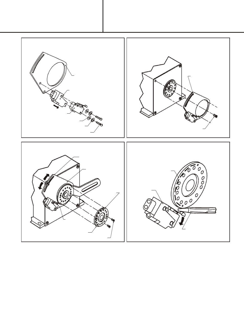
SWITCH MOUNTING
PLATE
PLASTIC INSULATING BOOT
(SLIDES OVER SWITCH)
SWITCH
WASHER (2)
LOCK WASHER (2)
#4.40 SCREW
SWITCH MOUNTING
PLATE
PHILLIPS SCREW
Fig. 2 - Assemble switch and plastic insulating boot
and attach to switch mounting plate.
Fig. 3 - Mount switch mounting plate on actuator.
Fig. 4 - Set circular switch cam for make/break points.
Fig. 5 - Bending the metal arm on the switch for
adjustment of switch make and break.
SCREWDRIVER BLADE
CIRCULAR SWITCH CAM
SWITCH
FINAL ADJUSTMENTS
REFERENCE
HOLES (2)
SWITCH MOUNTING
PLATE
SCREWS
SWITCH
ARM LOOP
CIRCULAR
SWITCH CAM
AD JUST MENT
If a finer adjustment is necessary, loosen the screw holding the switch mounting plate on the actuator and move the switch
mounting place to correctly place the switch arm loop on the circular switch cam. Carefully tighten the Phillips screw. Do
not over torque the screw to prevent stripping the actuator plastic case threads.