Wiring dia gram, Commer cial split system heat pump three phase, Figure 6. t5bp wiring diagram – Reznor T5BP Unit Installation Manual User Manual
Page 16
16
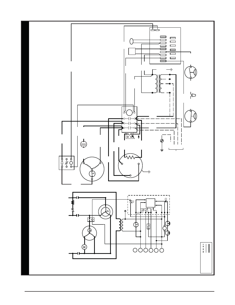
Figure 6. T5BP Wiring Diagram
7109690
09/09
FIELD WIRING
LEGEND:
LO
W V
O
LT
A
G
E
HIGH V
O
LT
A
G
E
¢710969V¤
Commer
cial Split System Heat Pump
Three Phase
NO
TES:
1.
Disconnect all po
wer bef
ore ser
vicing.
2.
For suppl
y connections,
use copper conductor
s onl
y
.
3.
Not suitab
le on systems that e
xceed 150 v
olts to gr
ound.
4.
For replacement wires,
use conductor
s suitab
le f
or 105°C
5.
For suppl
y wire ampacities and o
ver
current pr
otection,
see unit data label.
6.
Furnace/Air Handler w/factor
y
equipped 24V contr
ol cir
cuit transf
ormer
s,
should be modified/re
wired to ONL
Y
use 24V transf
ormer fr
om outdoor
section.
See installation instructions f
or typical modifications.
1.
Couper le courant a
v
ant de faire letretien.
2.
Emplo
y
ez uniquement des conducteur
s en cuivre
3.
Ne con
vient pas aux installations de plus de 150
v
olt a la terre
.
DEFR
OST BO
ARD OPERA
T
ION
1)Closes dur
ing defrost.
Rating:
1 Amp
. Max.
2)Opens dur
ing defrost.
Rating:
2 HP
. at 230
V
a
c Max.
3)Closed when
“Y”
is on.
Open
when
“Y”
is off
. Pro
vides
“off
”
dela
y time of 5 mins
. when
“Y”
opens
.
4)With DFT closed and
“Y”
closed, compressor r
u
n time is
accum
u
lated.
Opening of DFT dur
ing defrost or inter
v
al
per
iod resets the inter
v
al to 0.
5)Ground on location pro
v
ided inside compressor
ter
m
inal bo
x.
CC - Contactor Coil
CCH - Cr
ankcase Heat
DFT - Defrost
Ther
mostat
R
VS - Re
v
ersing
V
alv
e Solenoid
LPS - Lo
w Pressure Switch
HPS - High Pressure Switch
CAS- Contactor A
uxilliar
y
Switch (1NO/1NC)
L1
L2
L3
CCH
CAS
CC
OUTDOOR
FA
N
M
O
T
O
R
CAP
A
CIT
O
R
RELA
Y
COMPRESSOR
CC
L2
L1
L3
C
S
R
CC
T3
T3
E
2
4
1
1
3
R
W2
O
Y
C
LOGIC
DEFR
OST CONTR
OL
BO
ARD
LO
W V
O
L
T
A
G
E
TERMINAL
LPS
HPS
SEE NO
TE 7
SEE NO
TE 9
SEE NO
TE 8
RV
S
DFT
DFT
DF2
DF1
R
W2
O
Y
C
T2
T1
CC
7.
Wires connected to normall
y
c
losed contacts.
8.
T
ransf
ormer primar
y
connection will matc
h unit
rated v
olta
g
e
.
9.
For 208V operation remo
ve white wire fr
om 230V tap
and place on 208V tap.
WIRING DIA
GRAM
OUTDOOR
F
AN MO
T
O
R
DEFR
OST
CONTR
O
L
BO
ARD
RELA
Y
COMPRESSOR
AU
X
.
SWITCH
CAP
A
CIT
OR
CONT
A
CT
OR
LO
W PRESSURE
SWITCH
HIGH PRESSURE
SWITCH
24
56
13
T1
T2
C
Y
O
W2
R
DFT
DFT1
DFT2
E
C
Y
O
W2
RE
ORANGE
BLA
CK
BLA
CK
REV
VA
LV
E
DFT
T1
T2
T3
L1
L2
L3
T2
T1
T3
BLACK
PURPLE
BROWN
BR
O
W
N
YELLO
W
YELLO
W
460
24V
SECOND
A
R
Y
230
208
TRANSFORMER
PRIMAR
Y
THREE PHASE
FIELD SUPPL
Y
GRD
L1
L2
L3
YELLO
W
BLA
CK
RED
ORANGE
WHITE
BLA
CK
BLA
CK
BLA
CK
BLA
CK
BLA
CK
BLACK
GREEN
RED
BLUE
BLUE
BR
O
W
N