Electrical information – Reznor T5BP Unit Installation Manual User Manual
Page 15
15
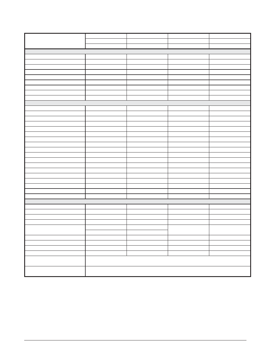
ELECTRICAL INFORMATION
Model
Number
T5BP-
090C
090D
120C
120D
208-230V
460V
208-230V
460V
920892
920893
920894
920895
PERFORMANCE DATA
Gross Cooling Capacity (95
o
F) Btuh
92,400
92,400
120,700
120,700
1
Net Cooling Capacity - Btuh
90,000
90,000
116,000
116,000
1
A.R.I. Rated Airfl ow - C.F.M.
3,000
3,000
4,000
4,000
2
Cooling - Effi ciency E.E.R. (Btu/Watt)
11.00
11.00
11.00
11.00
3
Cooling - Effi ciency I.E.E.R.
11.80
11.80
11.50
11.50
Gross Heating Capacity (47˚F) - Btuh
86,000
86,000
107,000
107,000
4
Heating - Effi ciency - C.O.P.
3.30
3.30
3.30
3.30
Gross Heating Capacity (17˚F) - Btuh
54,000
54,000
70,000
70,000
4
Heating - Effi ciency - C.O.P.
2.40
2.40
2.40
2.40
ELECTRICAL RATINGS
Volts / Phase / Hz.
208-230 / 3 / 60
460 / 3 / 60
208-230 / 3 / 60
460 / 3 / 60
Operating Voltage
187-253
414-506
187-253
414-506
Unit Rated Ampacity
28.3
13.9
33.4
18.4
Minimum Circuit Ampacity (MCA)
34.6
17.0
40.9
22.6
5
Max. Overcurrent Protection (MOP)
50
25
70
35
Compressor Data:
1 ea.
1 ea.
1 ea.
1 ea.
Compressor(s) (Scrolls)
ZP83KCE-TF5
ZP83KCE-TFD
ZP103KCE-TF5
ZP103KCE-TFD
Volts / Phase /Hz.
208-230 / 3 / 60
460 / 3 / 60
208-230 / 3 / 60
460 / 3 / 60
Rated Load Amps (RLA)
25.0
12.2
30.1
16.7
Lock Rotor Amps (LRA)
164
100
225
114
Stages / Percent
1 / 100
1 / 100
1 / 100
1 / 100
Crankcase Heater - Qty. / Type
1 / Band
1 / Band
1 / Band
1 / Band
Outdoor Fan Assembly:
1 ea.
1 ea.
1 ea.
1 ea.
Volts / Phase /Hz.
208-230 / 1 / 60
460 / 1 / 60
208-230 / 1 / 60
460 / 1 / 60
Motor - HP / RPM
3/4 - 875
3/4 - 875
3/4 - 875
3/4 - 875
Motor Amps
3.3
1.7
3.3
1.7
Fan Blade - Diameter / Pitch / # Blades
30” / 22 / 3
30” / 22 / 3
30” / 26 / 3
30” / 26 / 3
RPM / CFM (Max. - Total)
850 - 7,200
850 - 7,200
850 - 8,000
850 - 8,000
PHYSICAL DATA & REFRIGERANT SPECS
Outdoor Coil Assembly:
1 ea.
1 ea.
1 ea.
1 ea.
Area (Ft.
2
)
31.94
31.94
38.33
38.33
Rows - FPI
2 - 16
2 - 16
2 - 18
2 - 18
Tube Diameter
3/8” OD
3/8” OD
3/8” OD
3/8” OD
Refrigerant Suction Line - Length / OD
0 - 75 Ft. / 1-1/8”
0 - 75 Ft. / 1-1/8”
0 - 100 Ft. / 1-3/8”
(7)
0 - 100 Ft. / 1-3/8”
(7)
76 - 100 Ft. / 1-3/8”
(7)
76 - 100 Ft. / 1-3/8”
(7)
Refrigerant Liquid Line - Length / OD
All Lengths - 5/8” OD
All Lengths - 5/8” OD
All Lengths - 5/8” OD
All Lengths - 5/8” OD
Refrigerant Charge
R410A
R410A
R410A
R410A
Holding Charge - (oz.)
90
90
90
90
6
Total System with 25’ Line Set
480
480
528
528
High Pressure Switch (PSIG)
Cut Out: 650 +/- 15
Cut In: 460 +/- 15
Loss of Charge Pressure Switch (PSIG)
Cut Out: 5 +/- 5
Cut In: 20 +/- 5
NOTE: Net capacity includes indoor blower motor heat deduction. Gross capacity does not include indoor blower motor heat deduction.
1
Certifi ed in accordance w/ A.R.I. Standard 340/360 at 95° F Outdoor DB and 80° F db/67° F wb evaporator entering air at minimum
external duct static pressures allowed by the standard.
2
E.E.R. - Energy Effi ciency Ratio. E.E.R. is determined @ 95˚F Outdoor DB & 80˚F DB / 67˚F WB Air Indoor
3
I.E.E.R. - Integrated Energy Effi ciency Ratio. Certifi ed in accordance with A.R.I. Standard 340/360.
4
C.O.P. - Coeffi cient of Performance.
5
Delay Fuse or HACR Type Circuit Breakers can be used.
6
Add / Subtract 9.0 oz. of refrigerant per 5 Ft. change in length from original 25 Ft. lineset total system charge.
7
Requires a 1-3/8” to 1-1/8” reducer line to unit.
Table 4. Electrical Specifi cations & Physical Data - 11.0 E.E.R. - 3 Phase / 60 Hz