Caution – Reznor R6GD Unit Installation Manual User Manual
Page 16
16
GAS SUPPLY AND PIPING
• All gas piping must be installed in compliance with
local codes and utility regulations. In the absence
of local codes the gas line installation must comply
with the latest edition of the National Fuel Gas Code
ANSI Z223.1 or CAN/CGA B149 Installation Codes.
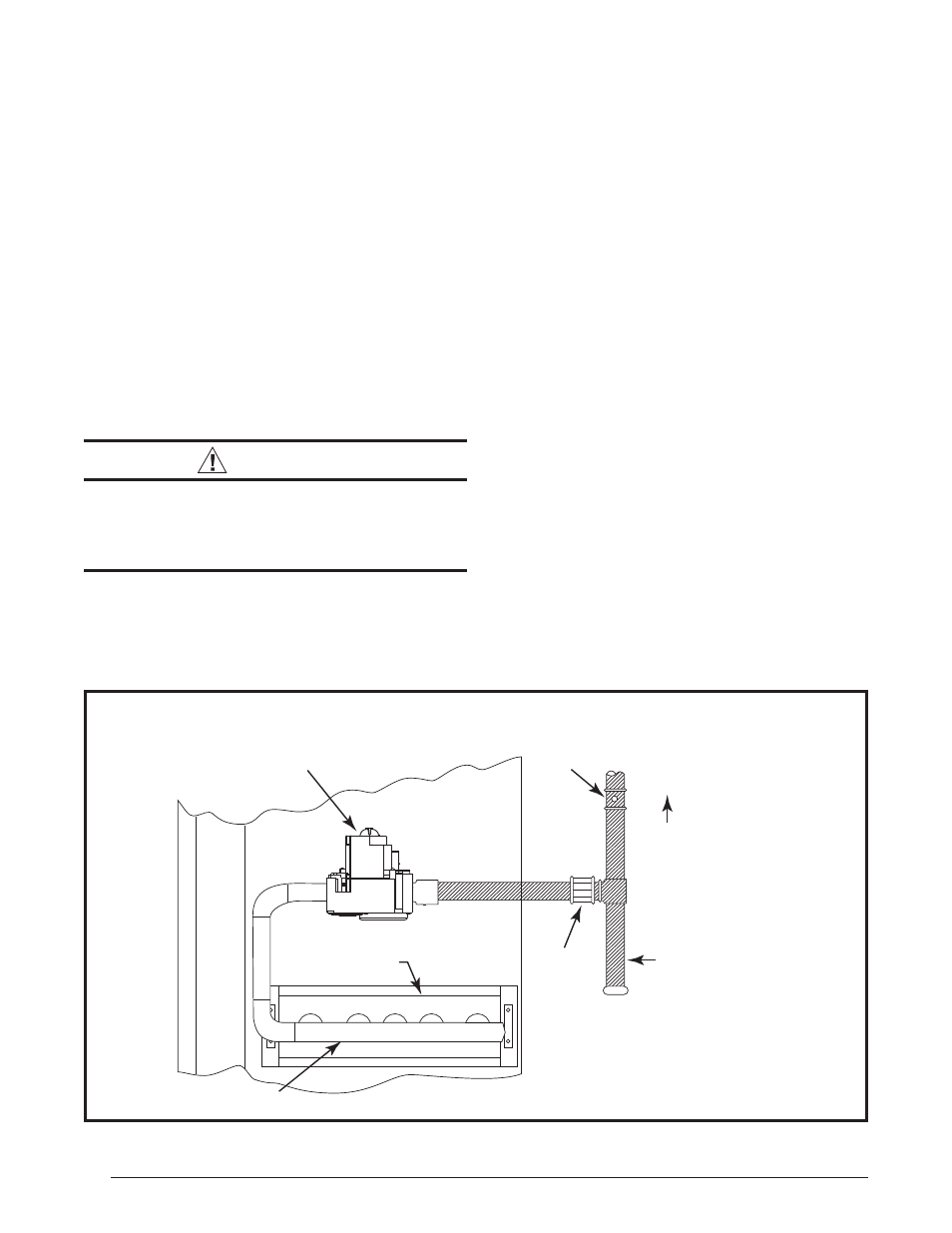
• Some local codes require the installation of a manual
main shut-off valve and ground joint union external
to the furnace (Figure 9). The shut-off valve should
be readily accessible for service and/or emergency
use. Consult the local utility or gas supplier for
additional requirements regarding placement of the
manual main gas shut-off.
• The manifold pressure must be set to the appropriate
value for your installation. Refer to the Manifold
Pressure Adjustment section (page 20) for
adjustment instructions.
• Gas piping must never run in or through air ducts,
chimneys, gas vents, or elevator shafts.
• Compounds used to seal joints on gas piping must
be resistant to the actions of LP propane gas.
• The main gas valve and main power disconnect to
the furnace must be properly labeled by the installer
in case emergency shutdown is required.
• An 1/8 inch NPT plugged tap must be installed in
the gas line immediately upstream of the gas supply
connection to the furnace for use when measuring
the gas supply pressure. The plug should be readily
accessible for service use.
• A drip leg should be installed in the vertical pipe
run to the unit (Figure 9).
Optional Humidistat
An optional humidistat may be installed in the return
air duct for humidity control (when needed), maximum
system capacity and energy effi ciency. The humidistat
senses when humidity in the return air stream is above
a preset level and sends a signal to the motor to reduce
airfl ow. This allows more moisture to be removed until the
humidity level drops.
NOTE: The packaged heat pump unit is pre-programmed
for humidistat operation. Remove the jumper connector
between the two terminals marked HUM on the variable
speed board.
Install the humidistat in the return air duct as directed in
the installation instructions included with the kit. Wire the
humidistat through the low-voltage wire entrance in the
packaged heat pump unit to the quick-connect terminals
marked HUM. Wire the humidistat to open on rise in
humidity.
CAUTION:
To avoid personal injury or property damage,
make certain that the motor leads cannot
come into contact with any uninsulated metal
components of the unit.
Check all factory wiring to the units wiring diagram. Inspect
the factory wiring connections to be sure none loosened
during shipping or installation.
Ground
Joint
Union
Dripleg
Shut-Off Valve
with 1/8 NPT
plugged tap
Burner
Assembly
Manifold
Some utilities
require Shut-Off
Valve to be
4 to 5 feet
above floor
Automatic Gas Valve
(with manual shut-off)
Figure 9. Typical Gas Hookup - Right Side Entry