Cautions, Figure 4 - coil cabinet module with dx coil, Figure 2 - wiring – Reznor RDH Option - Installation - UV Light Installation - PreevA User Manual
Page 3
Form I-PREEVA-UV, P/N 220705, Page 3
5. Install the ultra-violet bulb(s).
CAUTIONS
Do not touch bulb glass without gloves. Oil from
fingerprints will permanently etch the glass and
weaken bulb structure. Clean bulb after handling.
Install the bulb BEFORE the power is applied.
Installing the bulb while power is on will trigger
the “end-of-lamp-life circuit”, and the bulb will
not light. If this happens, shut off power, wait ten
minutes, and turn power on. Bulb should light.
The bulb is shipped in its original carton which is cable tied to the
installed light fixture. See
FIGURE 3. Grasping only the ends of
the bulb (not the glass), remove it from the package.
Using a lint free cloth and isopropyl alcohol, clean the bulb. Fin-
gerprints on a bulb will permanently damage it. Push the bulb
into place until it is seated. Rotate 90° until two distinct clicks
are heard.
FIGURE 3 - Bulb Shipping
Location in Blower Section
Bulbs)
are shipped
in their original car-
ton and require field
installation. Read
cautions before
removing
bulb.
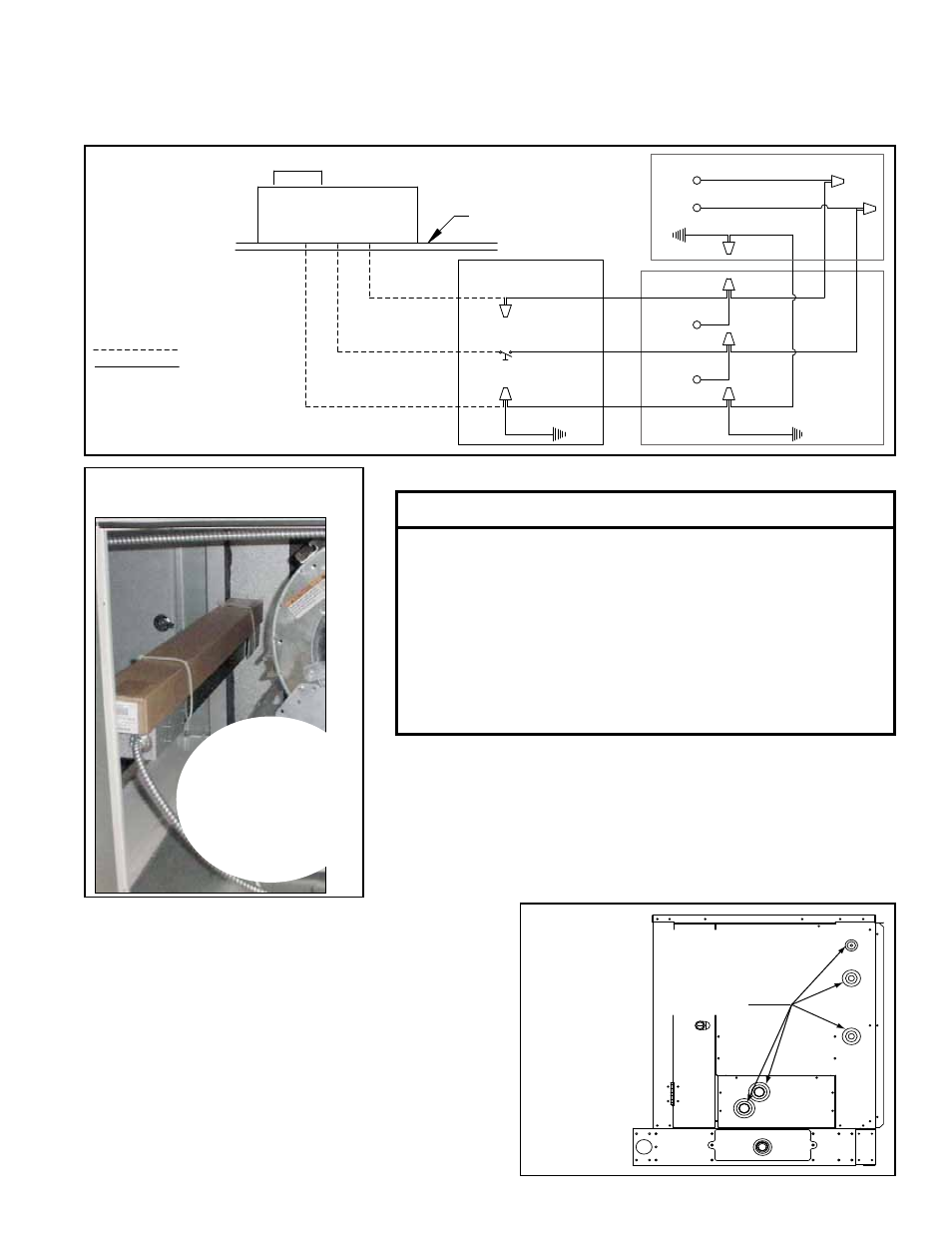
b) Refer to the wiring diagram in FIGURE 2 and run field-supplied 14 gauge
wiring from the disconnect switch location, through the factory-installed con-
duit, to the junction box for the blower door interlock switch.
c) Install the disconnect switch and connect the wires.
If a connection opening
is not used, remove
that grommet and
replace it with
a hole plug.
FIGURE 4 -
Coil Cabinet
Module with
DX Coil
6. DX Coil Only - Plug all unused openings.
If the unit has a DX coil, all openings in the cooling
coil module for line connections must be used or
plugged. If any openings are unused, remove the
factory-installed grommet and replace it with the
appropriate size hole plug provided in the plastic
parts bag. See
FIGURE 4.
7. Test bulb. Wear safety glasses and cover skin.
Standing as far away as possible, turn power on to
the light and depress door interlock switch. If bulb
glows with a blue hue, turn off power. If bulb does
not glow, turn off the power and find the cause.
BLOWER DOOR
INTERLOCK SWITCH
Models 175-400 only
Lamp Ballast #2
Lamp
Ballast #1
- Applies to
All Sizes
2 x 4 JUNCTION BOX
FIELD SUPPLIED
FUSED DISCONNECT
LINE/1/60
Field Connection
Panel
OPTION UV2 WIRING
(UVC Lights are located in
the blower compartment.)
#14 Ga
White
#14 Ga
Black
#14 Ga White
#14 Ga
Green
#14 Ga Black
#14 Ga White
#14 Ga Black
GRD
#14 Ga
Green
GRD
GRD
Field wiring
Factory wiring
#14 Ga
Black
#14 Ga
Green
#14 Ga
Green
#14 Ga
Green
#14 Ga White
#14 Ga
Black
#14 Ga
Green
#14 Ga Green
FIGURE 2 -
Wiring