Caution, Installation instructions, Safety considerations (cont’d) – Reznor RDH Option - Installation - UV Light Installation - PreevA User Manual
Page 2: Location and components
Page 2
CAUTION
Do not touch bulb glass without gloves.
Oil from fingerprints will permanently
etch glass of bulb and weaken structure.
Clean bulb after handling.
CAUTION
Bulb contains a small amount of
mercury. If a bulb breaks, clean with
care and dispose of using an envi-
ronmentally safe disposal method.
The Option UV2 light is factory-installed in the blower section, downstream of the
cooling coil. PREEVA Sizes 75-150 have one light fixture; Sizes 175-400 have
two. The bulb(s) are shipped in the blower section attached to each fixture but not
installed for use. When handling a bulb, wear gloves and DO NOT TOUCH the
glass; handle only on the ends.
In units with a DX coil, there will also be a parts bag containing three hole plugs.
Field-supplied components include a disconnect switch, 14 gauge wiring, metal
conduit or aluminum tape, and conduit connection or wire bushing.
Installation
Instructions
1. Turn off all power to the unit. Open the blower and electrical compartment
doors.
2. Ultra-violet light may damage certain plastics and exposed non-UVC protected
wires. Any field-supplied wiring or plastics in the blower compartment must be
wrapped with aluminum tape or installed in metal conduit.
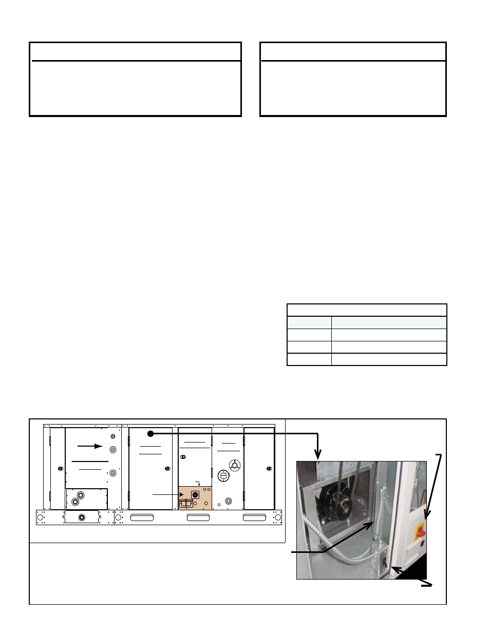
Field
Connection
Panel
NOTE: The field connection panel is shown above with a unit on/off switch and a convenience outlet.
Both are optional and may not be on the unit being installed.
Mark and
drill hole(s)
for attaching
disconnect
switch.
Cooling Coil
Module
Blower
Section
Heat
Section
Electrical
Compartment
Airflow
FIGURE 1 -
Location and
Installation of
Field-Supplied
Disconnect Switch
Install disconnect switch wiring. Refer to the wiring diagram
in FIGURE 2. Wiring must be 14 gauge. Run wires from the
disconnect switch location through the factory-supplied con-
duit at the electrical compartment wall to the blower door
interlock switch junction box.
Example of one type of
field-installed UV light
disconnect switch
Factory-installed blower
door safety interlock switch
Safety Considerations (cont’d)
3. A separate, dedicated power
supply must be used for the
Option UV2 light. Do not use unit
wiring or control box connec-
tions.
Wiring must comply with national
and local codes. Power source
must be a suitable fused,
grounded, protected source with
the correct voltage. Voltages other than
115/1, 208/1, 230/1 will permanently
damage the lamp. Wire per
TABLE 1.
TABLE 1 - Supply Wiring
Wiring
Wire Color
Power
Black
Neutral
White
Ground
Green
4. Install the field-supplied disconnect switch. See FIGURE 1 and follow
instructions.
a) Locate the field connection panel. Mark and drill hole(s) for attaching field-
supplied disconnect switch .
Location and
Components